Intravascular device

a technology of intravascular device and lead element, which is applied in the field of intravascular device, can solve the problems of reducing the risk of continued canalization or recanalization, and limited size, and achieves the effect of more precise localization of lead elemen

Inactive Publication Date: 2006-02-07
BOARD OF RGT THE UNIV OF TEXAS SYST
View PDF29 Cites 49 Cited by
  • Summary
  • Abstract
  • Description
  • Claims
  • Application Information

AI Technical Summary

Benefits of technology

[0014]The present invention relates to a multi-element intravascular occlusion device comprising at least one lead element attached to at least one anchoring element by at least one fiber. The lead element can be either a particle or a coil. Likewise, the anchoring element can be either a particle or a coil. Interference of flow created by the fiber linking the elements will exceed the sum of the effect of the separate elements. Instead of clotting on a single particle or coil, the blood clots around each part of the device. The resulting occlusion is deeper and thus decreases the risk of continued canalization or recanalization.
[0015]The present invention will also save time and money. Instead of requiring the placement of several coils or particles to achieve occlusion, the device allows a more rapid occlusion with fewer deployments. The device can be placed into a vessel by conventional means to create thrombosis and thereby occlude continued blood flow.
[0023]In another embodiment, the trailing element may function only to assist in detachment of the lead element. Alternatively, the trailing element may even detach from the lead element allowing more precise localization of the lead element without requiring that the trailing element be deposited in the vessel with the lead element.

Problems solved by technology

The resulting occlusion is deeper and thus decreases the risk of continued canalization or recanalization.
Typically, the size will be limited by the catheter used to place the occlusion device.

Method used


Image

  • Intravascular device
  • Intravascular device
  • Intravascular device

Examples


first embodiment

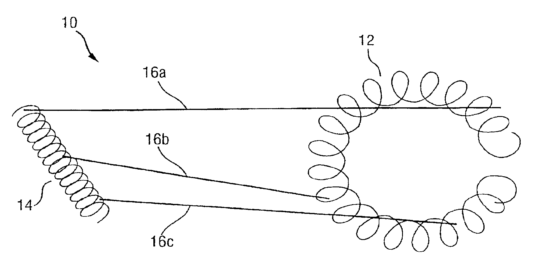
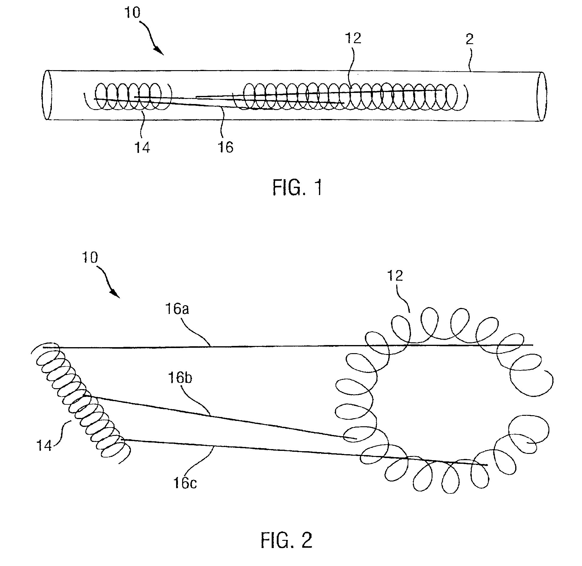
[0037]The present invention relates to a multi-element intravascular occlusion device which overcomes many of the disadvantages in the prior art. FIGS. 1 and 2 illustrate the device 10 in both a compressed and a deployed configuration. The device 10 comprises an anchoring element 12 and a lead element 14 connected by fibers 16, wherein both elements are coils. An introducing catheter 2 is used to place the device 10 into a blood vessel. As the device 10 is placed in the vessel, the anchoring element 12 deploys and lodges against the wall of the vessel. The blood flow carries the lead element 14 distally up to the length of the fibers 16. Blood clots form around the anchoring element 12, the fibers 16 and the lead element 14 to occlude blood flow through the vessel.

[0038]The potential shape of the coils are unlimited. Currently, numerous configurations of coils exist. For example, a “Gianturco coil” by Cook, Inc. includes multiple turns into a spring-like shape. Another coil, the Flo...

second embodiment

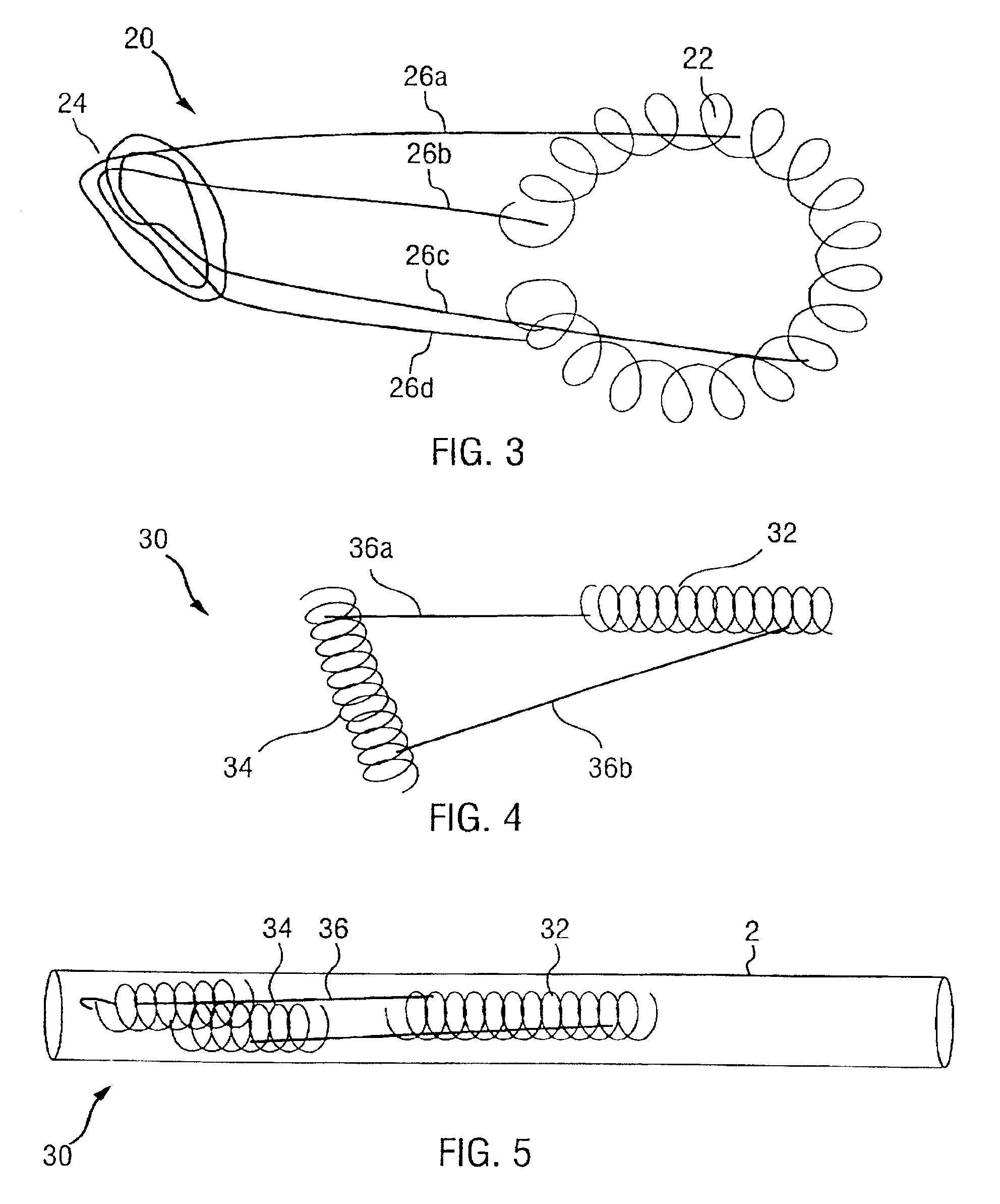
[0042]FIG. 3 illustrates occlusion device 20 which represents the present invention. The occlusion device 20 comprises an anchoring element 22 and a lead element 24 connected by fibers 26a, 26b, 26c, 26d. The anchoring element 22 comprises a coil similar to that shown in FIG. 2. The lead element 24, however, is formed by an intermeshing of fibers 26. The distance between the lead element 24 and the anchoring element 22 can be controlled both by the length of the fibers 26 and the location at which the fibers are intermeshed. The fibers 26 may be held together by a knot, or by some other means such as glue.

[0043]The lead element 24, as illustrated, acts like a thrombosis producing particle. Therefore, the lead element 24 can be any other thrombosis producing particle such as polyvinyl alcohol, silicone polymer, protein particles, glass beads, latex beads, or silk suture material.

third embodiment

[0044]FIGS. 4 and 5 illustrate occlusion device 20 which represents the present invention. Again, the occlusion device 30 comprises an anchoring element 32 and a lead element 34 connected by two fibers 36a, 36b. Both the lead and anchoring elements 32, 34, are shown as straight coils. As shown, fiber 36a is shorter than fiber 36b. Both fibers can be attached to any part of either element. Fibers 36a and 36b are attached to opposite ends of each coil. By varying the numbers of fibers 36 and where they attach the other elements, the behavior of the lead element 34 can be altered.

[0045]The mechanism of delivery for device 10, 20, 30 can incorporate any of the currently available mechanisms. These include either mechanical pushing of the coil through the introducing catheter 2 by a guide wire, injection of the coil using saline or other liquid to wash it from the introducing catheter 2, or use of a detachment apparatus which allows for controlled delivery or withdrawal. Utilization of t...


PUM


Abstract

A multi-element occlusion device (10, 20, 30, 40) provides an improvement over existing systems by increasing the occupation of a vascular lumen. The device (10, 20, 30) comprises an anchoring element (12, 22, 32), a lead element (14, 24, 34) and at least one fiber (16, 26, 36) attaching said elements. The elements and fibers produce a cumulative occlusive effect greater than the sum of the individual elements. When placed in the blood stream, the anchoring element (12, 22, 32) lodges against the vessel wall and the lead element (14, 24, 34) is carried to a position distal thereto. In another embodiment, an “umbrella” of support members extend from the lead element. A fabric web extends between these support members. The umbrella intravascular device expands upon its exit from the catheter. The fabric web produces complete occlusion of the vessel without the need for thrombosis to form between the elements. With the use of multi-element deployment, the device decreases the risk of continued canalization and recanalization.

Description

[0001]This is a divisional of application Ser. No. 08 / 662,845 filed Jun. 12, 1996 now U.S. Pat. No. 5,693,067 which is a divisional of application Ser. No. 08 / 164,398 filed Dec. 9, 1993 now U.S. Pat. No. 5,527,338, which is a continuation-in-part of application Ser. No. 07 / 939,296 filed Sep. 2, 1992 now U.S. Pat. No. 5,443,478. The entire text of each of the above-referenced disclosures is specifically incorporated by reference herein without disclaimer.[0002]The present application is a continuation-in-part of co-pending application Ser. No. 07 / 939,296, filed on Sep. 2, 1992, and entitled “Multi-Element Intravascular Occlusion Device.”FIELD OF THE INVENTION[0003]This invention relates to devices for placement within blood vessels for the purpose of permanent occupancy at a controlled location in the blood vessel by the device. The most frequent current use of such devices is vaso-occlusion by metallic coils delivered through a catheter to the site of occlusion.BACKGROUND OF THE INV...

Claims


Application Information

Patent Timeline
Patent Type & Authority Patents(United States)
IPC IPC(8): A61M29/00A61B17/12
CPCA61B17/12022A61B17/12109A61B17/12113A61B17/12168A61B17/12172
Inventor PURDY, PHILLIP D.
Owner BOARD OF RGT THE UNIV OF TEXAS SYST
Why Eureka
Try Eureka