Eureka AIR delivers breakthrough ideas for toughest innovation challenges, trusted by R&D personnel around the world.

Polyaxial pedicle screw having a threaded and tapered compression locking mechanism

a technology of compression locking and pedicle screw, which is applied in the direction of ligaments, prostheses, osteosynthesis devices, etc., can solve the problems of increasing operating time, limiting the range of motion, and considerable difficulty in inserting screws, and achieves the effect of increasing the crush locking effect on the screw head

Inactive Publication Date: 2006-05-02
FASTENETIX L L C
View PDF7 Cites 296 Cited by
  • Summary
  • Abstract
  • Description
  • Claims
  • Application Information

AI Technical Summary

Benefits of technology

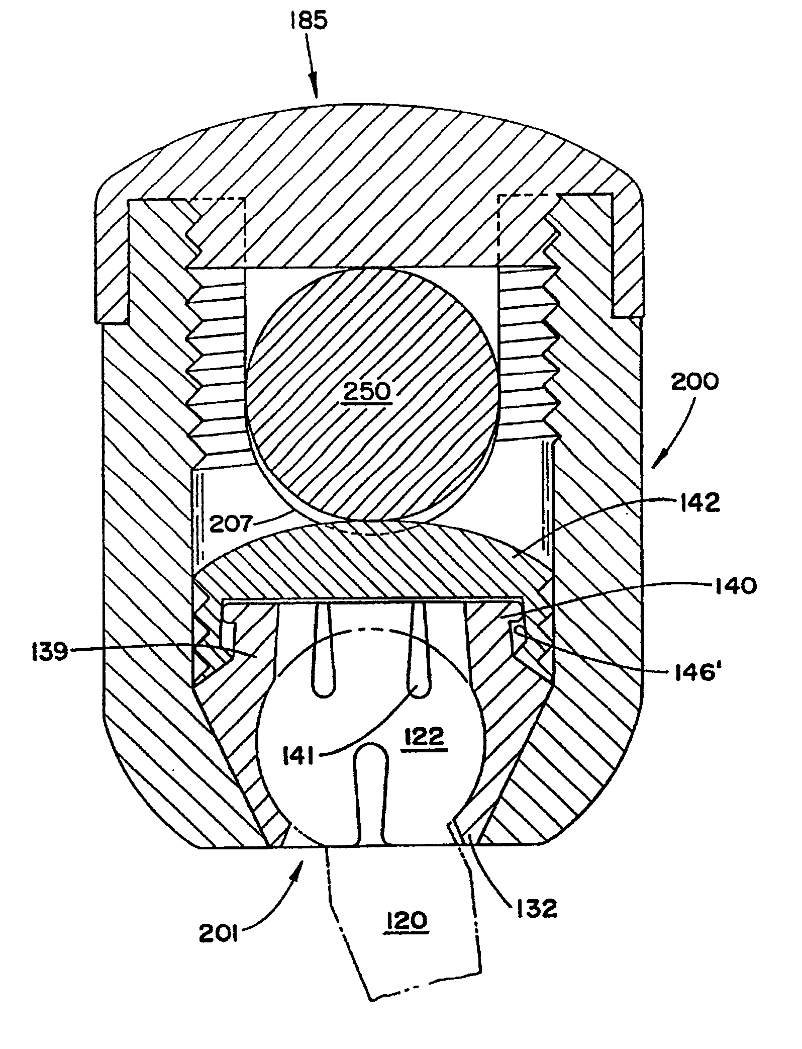
[0023]In a preferred variation of this embodiment, the interior surface of the cap portion includes a slight narrowing taper so that as the cap is compressed downward by the rod, the upper slots of the socket portion are also narrowed, further increasing the crush locking effect on the head of the screw.
[0024]The implantation of this screw by a surgeon may proceed first by the assembly of the screw into its initial state. The shaft of the screw is then driven into the vertebral bone at the desired angulation. A rod is then introduced into the rod receiving channel, and the body is angulated into the most ideal position for receiving the rod. A nut and / or set screw is then used to secure the rod in the channel, and simultaneously to provide a sufficient downward translational force to cause the socket portion to be driven into the tapered portion of the chamber in the axial bore, and further to cause the cap portion to drive downwardly also (this further compression locking the screw head in the embodiment wherein the sliding of the cap portion toward the socket portion provides an additional compression on the top of the socket portion and therefore onto the head of the screw).

Problems solved by technology

Genetic or developmental irregularities, trauma, chronic stress, tumors, and disease, however, can result in spinal pathologies which either limit this range of motion, or which threaten the critical elements of the nervous system housed within the spinal column.
It has been identified, however, that a considerable difficulty is associated with inserting screws long a misaligned curvature and simultaneously exactly positioning the coupling elements such that the rod receiving portions thereof are aligned so that the rod can be passed therethrough without distorting the screws.
Attempts at achieving proper alignment with fixed screws is understood to require increased operating time, which is known to enhance many complications associated with surgery.
Often surgical efforts with such fixed axes devices cannot be achieved, thereby rendering such instrumentation attempts entirely unsuccessful.
These teachings, however, are generally complex, inadequately reliable, and lack long-term durability.
These considerable drawbacks associated with prior art systems also include difficulty properly positioned the rod and coupling elements, and the tedious manipulation of the many small parts in the operative environment.

Method used


Image

  • Polyaxial pedicle screw having a threaded and tapered compression locking mechanism
  • Polyaxial pedicle screw having a threaded and tapered compression locking mechanism
  • Polyaxial pedicle screw having a threaded and tapered compression locking mechanism

Examples


Embodiment Construction

[0037]While the present invention will be described more fully hereinafter with reference to the accompanying drawings, in which particular embodiments and methods of implantation are shown, it is to be understood at the outset that persons skilled in the art may modify the invention herein described while achieving the functions and results of this invention. Accordingly, the descriptions which follow are to be understood as illustrative and exemplary of specific structures, aspects and features within the broad scope of the present invention and not as limiting of such broad scope.

[0038]Referring now to FIG. 4, a side view of the screw portion of the present invention, comprising a curvate head, is shown. The screw 120 comprises a head portion 122, a neck 124, and a shaft 126. In FIG. 4, the shaft 126 is shown as having a tapered shape with a high pitch thread 128. It shall be understood that a variety of shaft designs are interchangeable with the present design. The specific choi...


PUM


Abstract

A polyaxial orthopedic device for use with rod implant apparatus includes a screw having a curvate head, a two-piece interlocking coupling element which mounts about the curvate head, and a rod receiving cylindrical body member having a tapered socket into which both the screw and the interlocking coupling element are securely nested. The interlocking coupling element includes a socket portion which is slotted and tapered so that when it is radially compressed by being driven downwardly into the tapered socket in the cylindrical body it crush locks to the screw. The securing of the rod in the body member provides the necessary downward force onto the socket portion through a contact force on the top of the cap portion. Prior to the rod being inserted, therefore, the screw head remains polyaxially free with respect to the coupling element and the body. In a preferred embodiment, the cap portion and the socket portion are formed and coupled in such a way that when the cap portion is compressed toward the socket portion, there is an additional inward radial force applied by the cap portion to the socket portion, thereby enhancing the total locking force onto the head of the screw.

Description

CROSS-REFERENCE TO PRIOR APPLICATION[0001]This application is a continuation of U.S. patent application Ser. No. 09 / 774,915, filed on Jan. 30, 2001, now U.S. Pat. No. RE 37,665, which is a reissue of U.S. Pat. No. 5,882,350 issued from U.S. patent application Ser. No. 09 / 002,535 filed on Jan 2, 1998, which is a continuation-in-part of U.S. patent application Ser. No. 08 / 843,972 filed on Apr. 17, 1997, now U.S. Pat. No. 5,888,204, which is a continuation-in-part of U.S. patent application Ser. No. 08 / 632,560 filed on Apr. 15, 1996, now U.S. Pat. No. 5,725,588, which is a continuation-in-part of U.S. patent application Ser. No. 08 / 421,087 filed on Apr. 13, 1995, now U.S. Pat. No. 5,520,690, U.S. patent application Ser. No. 09 / 002,535 filed on Jan. 2, 1998, now U.S. Pat. No. 5,882,530 is also a continuation of U.S. patent application Ser. No. 08 / 835,909 filed Apr. 10, 1997, now abandoned, which is a continuation-in-part of prior application U.S. Ser. No. 08 / 663,383, entitled “A Polyaxi...

Claims


Application Information

Patent Timeline
Patent Type & Authority Patents(United States)
IPC IPC(8): A61B17/70A61B17/80A61B17/86A61F2/00A61F2/30A61F2/34A61F2/46
CPCA61B17/7032A61B17/7037A61F2/30744A61F2/34A61F2/4611A61F2002/3021A61F2002/30329A61F2002/30332A61F2002/30378A61F2002/30495A61F2002/30594A61F2002/30787A61F2002/3401A61F2220/0025A61F2220/0033A61F2230/0067A61F2310/00017A61F2310/00023A61B17/70
Inventor RALPH, JAMES D.TATAR, STEPHENERRICO, JOSEPH P.ERRICO, THOMAS J.
Owner FASTENETIX L L C
Why Eureka
Eureka Blog
Learn More