Monolithic optical compensation device for improved viewing angle in liquid crystal displays

a liquid crystal display and optical compensation technology, applied in static indicating devices, instruments, polarising elements, etc., can solve the problems of loss of contrast ratio, loss of contrast, and amount of light leakage through the display, so as to achieve good contrast, improve the quality of output, and improve the quality of image.

Inactive Publication Date: 2007-08-21
TELEDYNE SCI & IMAGING
View PDF17 Cites 3 Cited by
  • Summary
  • Abstract
  • Description
  • Claims
  • Application Information

AI Technical Summary

Benefits of technology

[0067]When viewed directly, a twisted nematic liquid crystal display provides high quality output, but at large viewing angles the image tends to degrade and exhibit poor contrast and gray scale nonuniformity. This occurs because the phase retardation effect of the liquid crystal material on light passing through it inherently varies with the inclination angle of the light, leading to a lower quality image at large viewing angles. By introducing one or more optical compensating elements in conjunction with the liquid crystal cell, however, it is possible to substantially correct for the undesirable angular effects and thereby maintain higher contrast and stable relative gray scale intensities at larger viewing angles than otherwise possible.

Problems solved by technology

The primary factor limiting the contrast achievable in a liquid crystal display is the amount of light which leaks through the display in the dark state.
This loss of contrast ratio is caused by light leaking through the black state pixel elements at large viewing angles.
In color liquid crystal displays, such leakage also causes severe color shifts for both saturated and gray scale colors.
The viewing zone of acceptable gray scale stability in a typical prior art twisted nematic liquid crystal display is severely limited because, in addition to color shifts caused by dark state leakage, the optical anisotropy of the liquid crystal molecules results in large variations in gray level transmission, i.e., a shift in the brightness-voltage curve, as a function of viewing angle.
These limitations are particularly important for applications requiring a very high quality display, such as in avionics, where viewing of cockpit displays from both pilot and copilot seating positions is important.
This phase dependence on incidence angle introduces an ellipticity to the polarization state which is incompletely extinguished by the second polarizer, giving rise to light leakage.
While the use of a C-plate compensator may be used to eliminate color desaturation, it does not improve gray scale stability.
The problem of maintaining constant gray scale luminance differences over the field of view relates substantially to the brightness level changes for levels assigned between the select (black for a normally white display) and nonselect (white for a normally white display) states.
The gray scale stability problem appears most predominantly when the vertical viewing angle varies.
Furthermore, negative C-plates can, for certain configurations, increase the contrast ratio at large fields of view, occasionally with some decrease in gray scale stability.
When viewed directly, a twisted nematic liquid crystal display provides high quality output, but at large viewing angles the image tends to degrade and exhibit poor contrast and gray scale nonuniformity.
This occurs because the phase retardation effect of the liquid crystal material on light passing through it inherently varies with the inclination angle of the light, leading to a lower quality image at large viewing angles.

Method used


Image

  • Monolithic optical compensation device for improved viewing angle in liquid crystal displays
  • Monolithic optical compensation device for improved viewing angle in liquid crystal displays
  • Monolithic optical compensation device for improved viewing angle in liquid crystal displays

Examples


Embodiment Construction

[0012]5.1 Overview of Liquid Crystal Display Structure

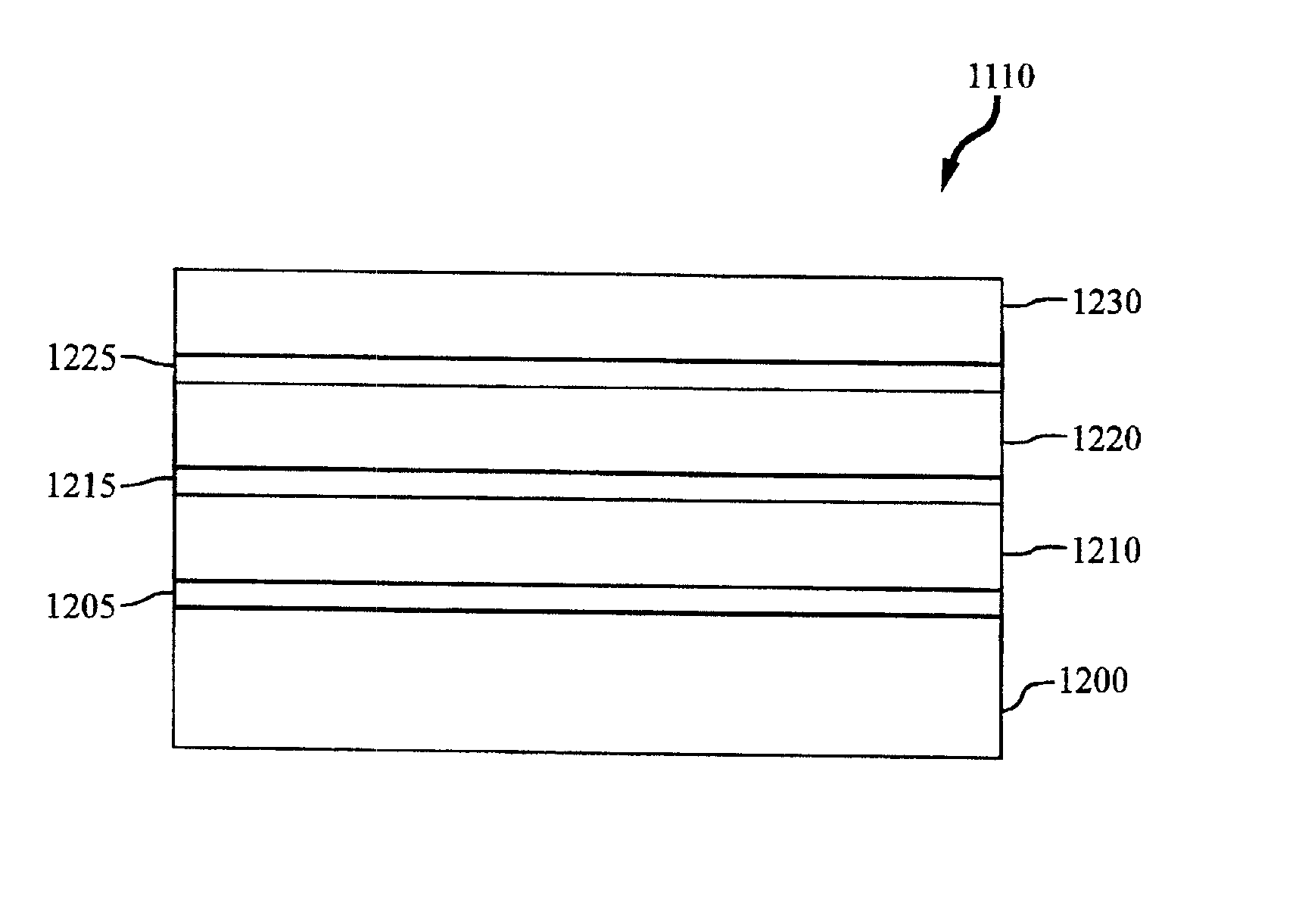
[0013]5.2 Monolithic Compensator Structure

[0014]5.3 Manufacture of the Monolithic Compensator

[0015]5.4 Advantages of the Monolithic Compensator

6. BIBLIOGRAPHY

7. CLAIMS

8. ABSTRACT

2. BACKGROUND OF THE INVENTION

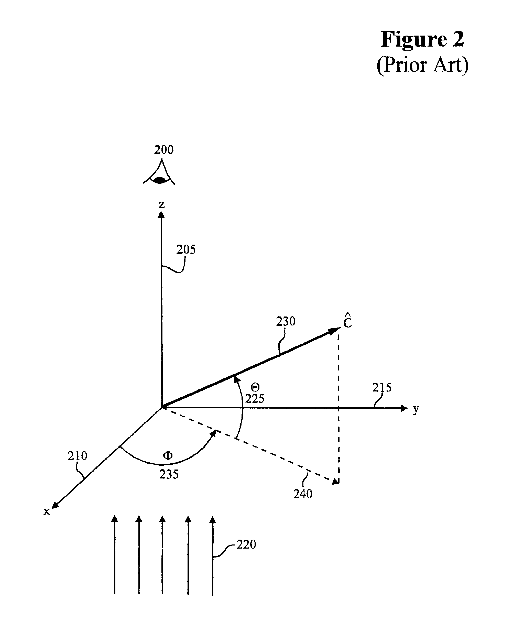
[0016]This invention is concerned with the design of liquid crystal displays (LCDs) and, more particularly, with techniques for maximizing the field of view of such displays by maintaining a high contrast ratio and minimal variance in relative gray levels over a wide range of viewing angles. These goals are achieved through the fabrication and manufacture of LCDs using a monolithic compensator device.

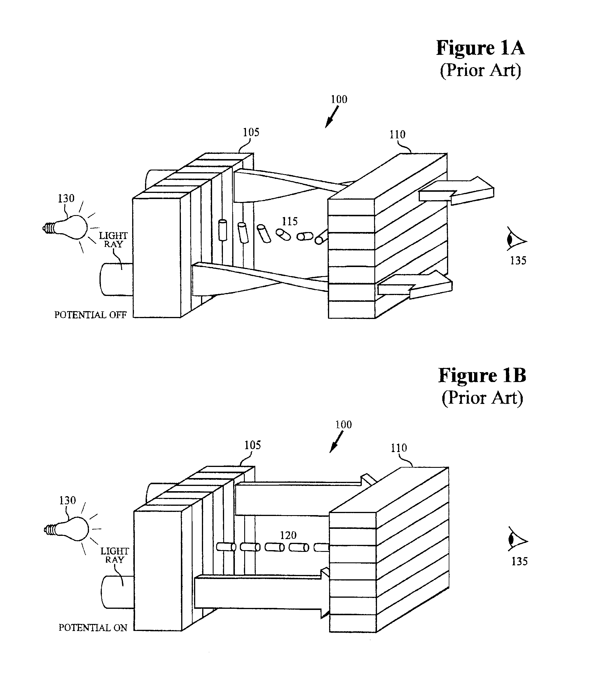
[0017]2.1 LCD Technology Overview

[0018]Liquid crystals are useful for electronic displays because polarized light traveling through a liquid crystal layer is affected by the layer's birefringence, which can be changed by the application of a voltage across the layer. By using this effect, the transmission or reflection of light f...


PUM

PropertyMeasurementUnit
angleaaaaaaaaaa
anglesaaaaaaaaaa
angleaaaaaaaaaa

Abstract

A monolithic O-plate optical compensator device, in accordance with the invention, comprises a plurality of thin-film compensation layers which are deposited on a single substrate. As used herein, the term “monolithic” is meant to imply that the O-plate and other thin-film compensator layers are formed by depositing (e.g., via solvent casting or vacuum deposition) one layer on top of another layer; with or without the use of surface modification treatments such as adhesion layers, alignment layers, and the like.

Description

[0001]This is a continuation-in-part application of U.S. patent application Ser. No. 223,251, filed Apr. 4, 1994, entitled “Optical Compensator for Improved Gray Scale Performance in Liquid Crystal Display,” now U.S. Pat. No. 5,504,603. In addition, U.S. Pat. No. 5,196,953 and the following contemporaneously filed U.S. patent applications are hereby incorporated by reference: (i) “Inorganic Thin Film Compensator For Improved Gray Scale Performance in Twisted Nematic Liquid Crystal Displays” by William J. Gunning, III, Bruce K. Winker, Donald B. Taber, Paul H. Kobrin, James C. Beedy, and John P. Eblen, Jr.; and (ii) “Organic Polymer O-Plate Compensator For Improved Gray Scale Performance in Twisted Nematic Liquid Crystal Displays” by Bruce K. Winker, Hong-Son Ryang, Leslie F. Warren, Jr., and Charles Rosenblatt, Zili Li, and Young J. Chung. All referenced patents and patent applications are commonly assigned with this application.TABLE OF CONTENTS[0002]1. REFERENCES[0003]2. BACKGROUN...

Claims


Application Information

Patent Timeline
Patent Type & Authority Patents(United States)
IPC IPC(8): G02F1/335G02F1/1333C23C14/22G02B5/30G02F1/133G02F1/1335G02F1/13363G02F1/1337
CPCC23C14/226G02B5/3083G02F1/133632G02F1/133634G02F1/133636G02F2413/105G02F1/1335
Inventor WINKER, BRUCE
Owner TELEDYNE SCI & IMAGING
Why Eureka
Try Eureka