Surface position location system and method

a position location and surface technology, applied in the field of surface position location system and method, can solve the problems of not being well suited to a complex shaped surface of either two or three dimensions, position detectors such as the devices disclosed in the greanias, and confined to displays or flat surfaces, so as to increase the comfort of holding the stylus, improve the probability of holding, and maximize the probability of holding the user

Inactive Publication Date: 2007-10-16
LEAPFROG ENTERPRISES
View PDF42 Cites 61 Cited by
  • Summary
  • Abstract
  • Description
  • Claims
  • Application Information

AI Technical Summary

Benefits of technology

[0023]The present invention also includes a probe assembly with a cable with two conductors. The proximate end conductor is coupled to the processor and the proximate end of the other conductor is connected to a signal neutral point. The stylus in turn is coupled to the cable and incorporates therein the distal ends of two conductors with the distal end of the conductor coupled to the processor disposed to receive signals from the layer when the contact points have signals selectively applied to them and the user positions the stylus in vicinity of a selected point on the surface. The distal end of the other conductor is disposed to be contacted by the user when holding the stylus to connect the user to the signal neutral point. To maximize the probability that the user holds the stylus making contact with the contact point, it is located externally and positioned to be contacted by the user during use of the stylus. Further improve that probability, and to increase the comfort of holding the stylus, an electrically conductive contact of a flexible conductive polymer is placed to encircle the stylus at a position to maximize the user's comfort when holding the stylus.

Problems solved by technology

These technologies are limited to displays or flat surfaces.
Position detectors such as the devices disclosed in the Greanias patents, that use many conductors arranged in a grid, are not well suited to a complex shaped surface of either two or three dimensions.
There are, at a minimum, difficulties in positioning and shaping the conductors to fit the contours of a complex shape.
The use of bar contacts or strings of resistors along substantially the entire edge of an object limits their usefulness on objects where the position on the entire surface needs to be detected.
Any variation in contact resistance or changes in contact resistance due to environmental factors are not accounted for and result in detection errors.
The Meadows device is susceptible to the effects of unwanted phantom styluses coupling to the surface.
These phantom styluses cause detection errors because the changes that they also produce cause changes in the driving circuit.
Such cables for the systems of the prior art would be rather large and cumbersome.
Further, connectors with a large number of contacts are expensive and reduce the overall reliability of any system that requires them.
Contacts that allow rotation, such as slip rings or commutators, become prohibitively complex and expensive as the number of connections rises above a small number.
Additionally, the multiple circuits required to drive grid arrays are complex and costly to manufacture.
Acoustic wave detectors provide a rugged position detection mechanism but are costly to implement.
Light wave detection mechanisms are limited to flat surfaces and are susceptible to dust and insects blocking the light paths.
Each of these acts and interacts with each other causing interference and background noise to each other, depending on the intensity of the background or interfering signal.
Thus, as is well known in devices that utilize an antenna as a device to detect an input signal, these atmospheric signals may interfere with the ability to detect and receive a signal of interest.
That added signal, and the multiple frequencies that it includes is also known to potentially add a level of inaccuracy in such a system, if the desired signal can be detected at all.

Method used


Image

  • Surface position location system and method
  • Surface position location system and method
  • Surface position location system and method

Examples


first embodiment

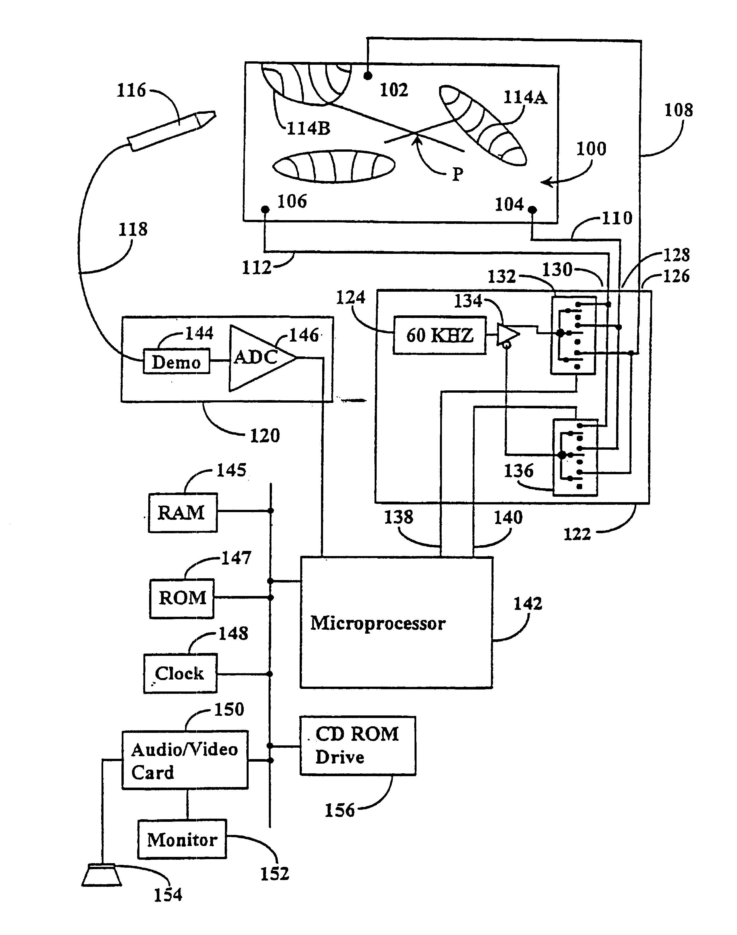
[0151]this aspect of the present invention is illustrated in FIG. 14b. In this view the connections at the proximate end of shielded cable 118 are the same as in FIG. 14a. At the distal end of stylus 116 there are some changes that have been made to effect the grounding of the user when holding stylus 116 to eliminate the parallel antenna effect inadvertently created by the user holding stylus 116 near center conductor / antenna 802′. Here it can be seen that the distal end of shielded cable 118, in addition to having center conductor 802′ exposed, has a portion of shield 800′ exposed. In addition, stylus 116 defines a hole 804 therethrough so that when a user holds stylus 116 a portion of one of the user's fingers must extend through hole 804 and make contact with shield 800′, thus grounding the user.

second embodiment

[0152]this aspect of the present invention is illustrated in FIGS. 14c and 14d with FIG. 14d showing a cut-away view of the distal end of stylus 116 to illustrate the internal configuration of this embodiment. In these views the connections at the proximate end of shielded cable 118 are the same as in FIGS. 14a and 14b. In FIG. 14c stylus 116 includes three portions: tip 810; main body 812; and conductive grip 806 that extends around stylus 116 at the point of the user's grasp. In FIG. 14d a portion of tip 810 and conductive grip 806 have been cutaway to illustrate the internal structure of the distal end of stylus 116. The internal arrangement is similar to that of FIG. 14b with the exception of the length of shield 800′ that has been exposed and dressing of a pig-tail 808 of shield 800′ back beneath conductive grip 806. Thus, when the user grasps stylus 116 with conductive grip 806 the user is grounded by the electrical interaction of conductive grip 806 and shield 800′ and pig-ta...


PUM


Abstract

An electrographic sensor unit and method for determining the position of a user selected position thereon. The electrographic sensor unit includes a layer of a conductive material having an electrical resistivity and a surface, at least three spaced apart contact points electrically interconnected with a layer of conductive material, a processor connected to the spaced apart contacts and disposed to selectively apply a signal to each of the contact points, and a probe assembly, that includes either a stylus of a flexible conductive layer spaced apart from the layer, coupled to the processor with the stylus disposed to be positioned by a user in vicinity of a user selected position on the surface of the layer, or that position being selected with a user's finger on the flexible layer and to receive signals from the layer when the contact points have signals selectively applied thereto. The user selected position is determined by the processor from signals received from the stylus, or flexible layer, each in relation to a similar excitation of different pairs of the contact points under control of the processor. The conductive layer may be either two or three dimensional and may be closed three dimensional shape. There may also be multiple layers with the processor being able to discern on which of those layers the user selected position is located. Further, provision is made to correct the calculated coordinates of the selected position for variations in contact resistance of each of the contact points individually. Additionally, a nonconductive skin having selected graphics printed thereon, such as a map, can be placed over the layer and the proces-sor further convert the calculated coordinates of the selected position to coordinates that relate to the graphical information printed in the skin, and even electro-nically (e.g., audio or visual) present information to the user relative to the graphical location selected as the selected position.

Description

[0001]This application is a Continuation-In-Partcontinuation application of U.S. Reissue patent application Ser. No. 09 / 796,685, filed Feb. 28, 2001, now RE 38,286 which is a reissue patent of Ser. No. 08 / 754,310, filed on Nov. 21, 1996, now U.S. Pat. No. 5,877,458, which is a continuation-in-part <?insert-end id="INS-S-00001" ?>application of an earlier filed co-pending patent application with the same title filed on Feb. 15, 1996, and given Ser. No. 08 / 601,719 which includes as an inventor the inventor of the present inventionis now U.S. Pat. No. 5,686,705, all of which are herein incorporated by reference in their entirety.FIELD OF THE INVENTION[0002]The present invention relates to a system and method for determining a location selected by a user on a surface and providing information to the user that has been determined to be relative to that location. In particular the present invention relates to position detection devices that are able to detect positions on a surface ...

Claims


Application Information

Patent Timeline
Patent Type & Authority Patents(United States)
IPC IPC(8): G09G5/00G06F3/033G06F3/045
CPCG06F3/045
Inventor FLOWERS, MARK
Owner LEAPFROG ENTERPRISES
Why Eureka
Try Eureka