Multi-layer forming fabric with stitching yarn pairs integrated into papermaking surface

a technology of papermaking surface and forming fabric, applied in the field of papermaking, can solve the problems of short service life of the fabric, less suitable as forming fabric, particularly problematic wire marking, etc., and achieve the effect of little distortion

Inactive Publication Date: 2008-02-19
WEAVEXX
View PDF19 Cites 7 Cited by
  • Summary
  • Abstract
  • Description
  • Claims
  • Application Information

AI Technical Summary

Benefits of technology

[0012]In view of the foregoing, it is an object of the present invention to provide a multi-layer forming fabric construction with little distortion in the top fabric layer.

Problems solved by technology

Wire marking is particularly problematic in the formation of fine paper grades, as it affects a host of paper properties, such as sheet mark, porosity, see through, and pin holing.
Regretably, such finely woven forming fabrics often are delicate and lack dimensional stability in either or both of the machine and cross machine directions (particularly during operation), leading to a short service life for the fabric.
In addition, a fine weave may adversely effect drainage properties of the fabric, thus rendering it less suitable as a forming fabric.
As a result, the appearance of paper formed with the fabric can be affected (sometimes adversely) by the presence of the stitching yarns.
In addition, triple layer fabrics have proven to have problems with interlayer wear.
This shifting can cause the fabric to wear and decrease in thickness, which can adversely affect the drainage of the fabric and, accordingly, its performance in papermaking.
These differences can induce the fabric to distort out-of-plane, which can in turn reduce the quality of paper produced with the fabric.
This balance can be quite difficult to strike.

Method used


Image

  • Multi-layer forming fabric with stitching yarn pairs integrated into papermaking surface
  • Multi-layer forming fabric with stitching yarn pairs integrated into papermaking surface
  • Multi-layer forming fabric with stitching yarn pairs integrated into papermaking surface

Examples


Embodiment Construction

[0027]The present invention will be described more particularly hereinafter with reference to the accompanying drawings. The invention is not intended to be to the illustrated embodiments; rather, these embodiments are intended to fully and completely disclose the invention to those skilled in this art.

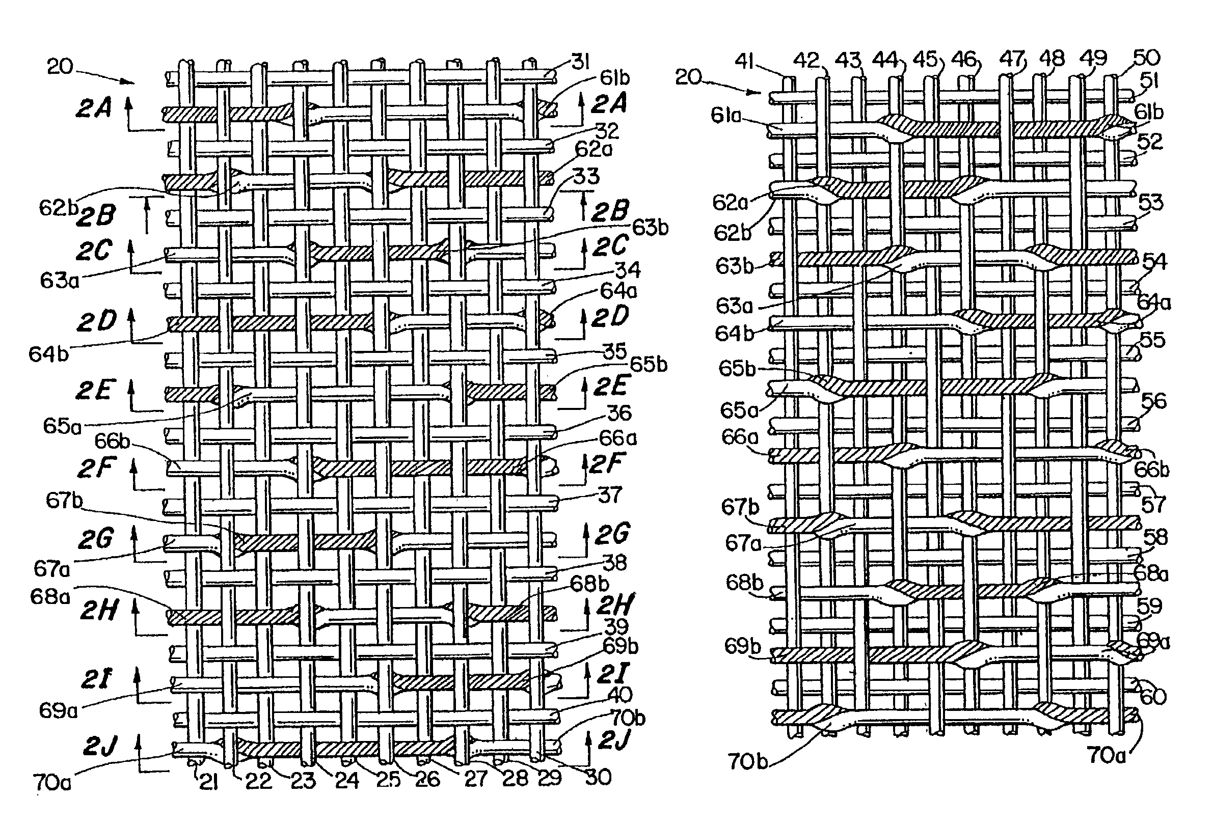
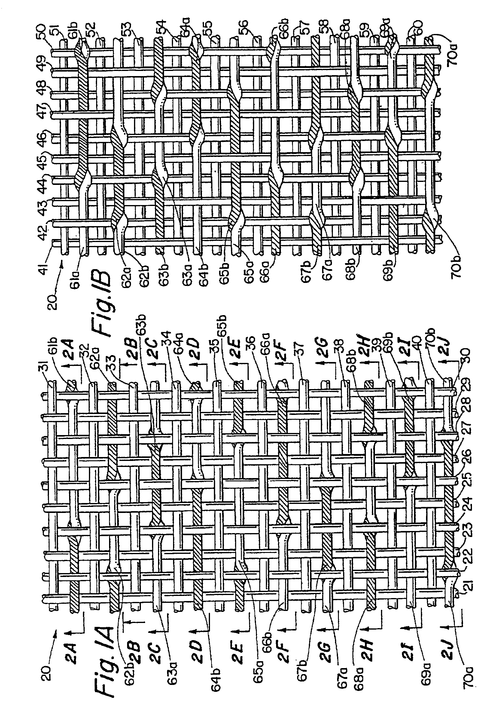
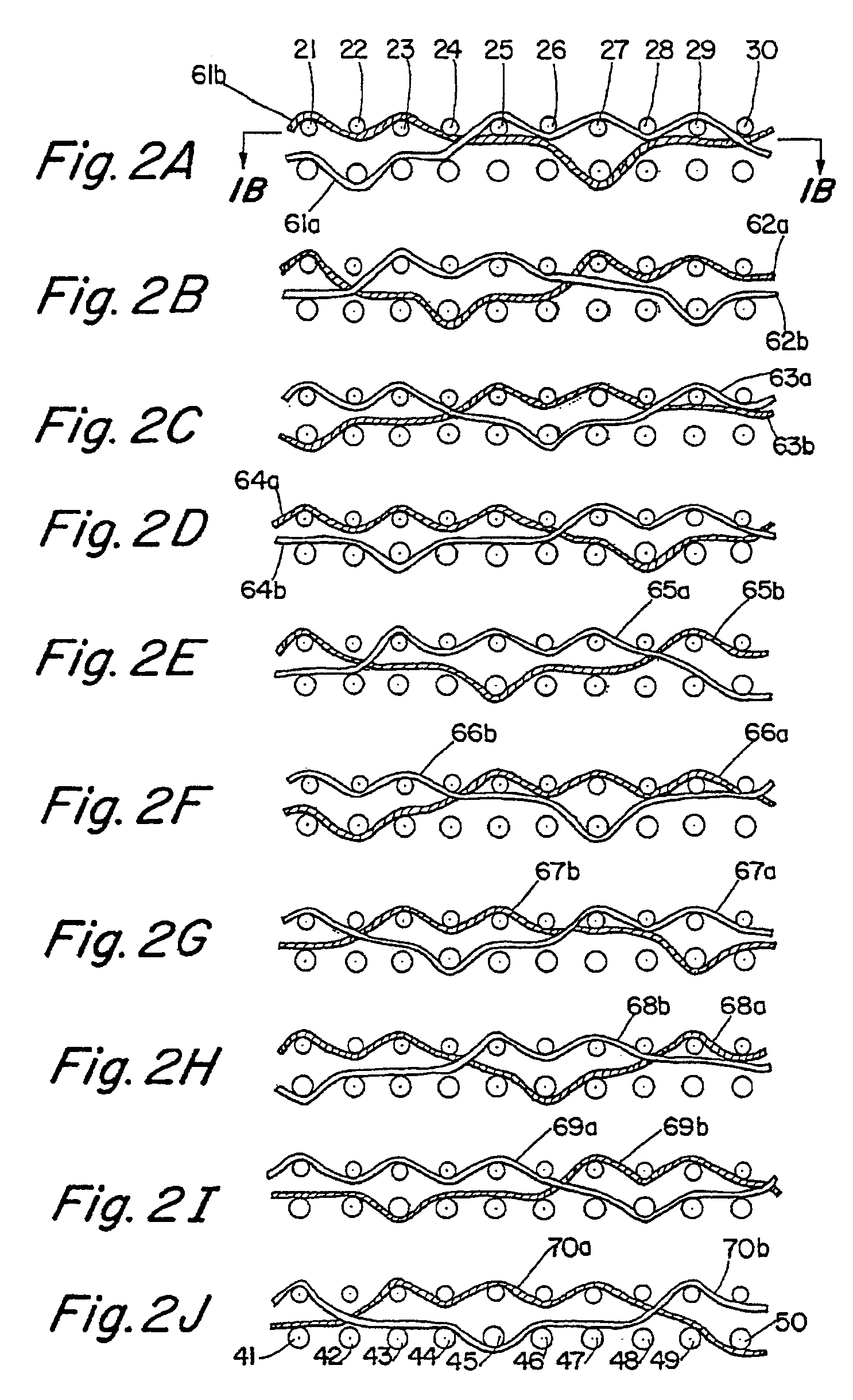
[0028]A 20 harness multi-layer forming fabric, generally designated at 20, is illustrated in FIGS. 1A and 1B, in which a single repeat unit of the fabric is shown. As seen in FIG. 1A, the repeat unit of the fabric 20 includes a top layer having ten top MD yarns 21-30 and ten top CMD yarns 31-40. These are interwoven such that each top CMD yarn passes over and beneath top MD yarns in an alternating fashion, with each top CMD yarn passing over and under the same top MD yarns. For example, top CMD yarn 31 passes under top MD yarn 21, over top MD yarn 22, under top MD yarn 23, over top MD yarn 24 and so on until it passes over top MD yarn 30. Similarly, top CMD yarn 32 passes under top MD...


PUM


Abstract

A multi-layer papermaker's forming fabric has stitching yarns integrated into the papermaking surface. Each of a plurality of repeating units of the fabric comprises: a set of top machine direction yarns; a set of top cross-machine direction yarns interwoven with the top machine direction yarns; a set of bottom machine direction yarns; a set of bottom cross-machine direction yarns interwoven with the bottom machine direction yarns; and pairs of first and second stitching yarns. The stitching yarns pairs are positioned between pairs of top cross-machine direction yarns. The stitching yarns of each pair are interwoven with the top and bottom machine direction yarns such that, as a fiber support portion of the first stitching yarn is interweaving with the top machine direction yarns, a binding portion of the second stitching yarn is positioned below the top machine direction yarns, and such that as a fiber support portion of the second stitching yarn is interweaving with the top machine direction yarns, a binding portion of the first stitching yarn is positioned below the top machine direction yarns. The first and second stitching yarns cross each other as they pass below a traditional top machine direction yarn. Also, each of the binding portions of the first and second stitching yarns passes below at least one of the bottom machine direction yarns. In this configuration, the stitching yarns are completely integrated into the top, or papermaking, surface of the fabric, and therefore do not adversely impact the papermaking qualities of the fabric.

Description

FIELD OF THE INVENTION[0001]The present invention relates generally to papermaking, and relates more specifically to fabrics employed in papermaking.BACKGROUND OF THE INVENTION[0002]In the conventional fourdrinier papermaking process, a water slurry, or suspension, of cellulosic fibers (known as the paper “stock”) is fed onto the top of the upper run of an endless belt of woven wire and / or synthetic material that travels between two or more rolls. The belt, often referred to as a “forming fabric,” provides a papermaking surface on the upper surface of its upper run which operates as a filter to separate the cellulosic fibers of the paper stock from the aqueous medium, thereby forming a wet paper web. The aqueous medium drains through mesh openings of the forming fabric, known as drainage holes, by gravity or vacuum located on the lower surface of the upper run (i.e., the “machine side”) of the fabric.[0003]After leaving the forming section, the paper web is transferred to a press se...

Claims


Application Information

Patent Timeline
Patent Type & Authority Patents(United States)
IPC IPC(8): D03D11/00D03D13/00D21F1/10D21F1/00
CPCD21F1/0045
Inventor WARD, KEVIN JOHN
Owner WEAVEXX
Why Eureka
Try Eureka