Acetabular component with improved liner seal and lock

a technology of acetabular components and seals, applied in the field of acetabular components with improved liner seals and locks, can solve the problems of damage to the bone into which the acetabular shell is inserted, debris can be generated, damage to the bone, etc., and achieve the effect of preventing the migration of poly debris

Inactive Publication Date: 2008-02-19
WHITESIDE BIOMECHANICS
View PDF18 Cites 10 Cited by
  • Summary
  • Abstract
  • Description
  • Claims
  • Application Information

AI Technical Summary

Benefits of technology

[0008]The acetabular component for a hip replacement system according to the present invention comprises an acetabular shell and liner, with an integrally formed seal and interlock. The seal is formed between the acetabular shell and the liner upon insertion and interlock of the liner into the acetabular shell. The seal is provided to substantially prevent a migration of poly debris along an interface of the outer surface of the l

Problems solved by technology

Acetabular shells typically have openings in the shell, including screw holes, which give rise to at least two problems.
First, wear debris that is generated from the articular movement between a femoral head component and the liner can migrate between the liner and the acetabular shell, pass through the openings in the acetabular shell, and cause damage to the bone into which the acetabular shell is implanted.
Second, debris can also be generated as a result of minor movement between the liner and the acetabular shell, commonly known as micromotion.
This debris can also pass through the openings in the acetabular shell and cause damage to the bone.
While these interlocking means serve to reduce the amount of debris generated by micromotion, they fail to solve the problem of migration of debris from the prosthetic articular surface between the acetabular shell and liner.
Thus, despite these efforts, large numbers of polyethylene particles still have access to the acetabular bone.
The main disadvantage of this approach is that the plugs fail to prevent the migration of debris through holes that have bone screws inserted therethrough.
The debris will still migrate around th

Method used


Image

  • Acetabular component with improved liner seal and lock
  • Acetabular component with improved liner seal and lock

Examples


Embodiment Construction

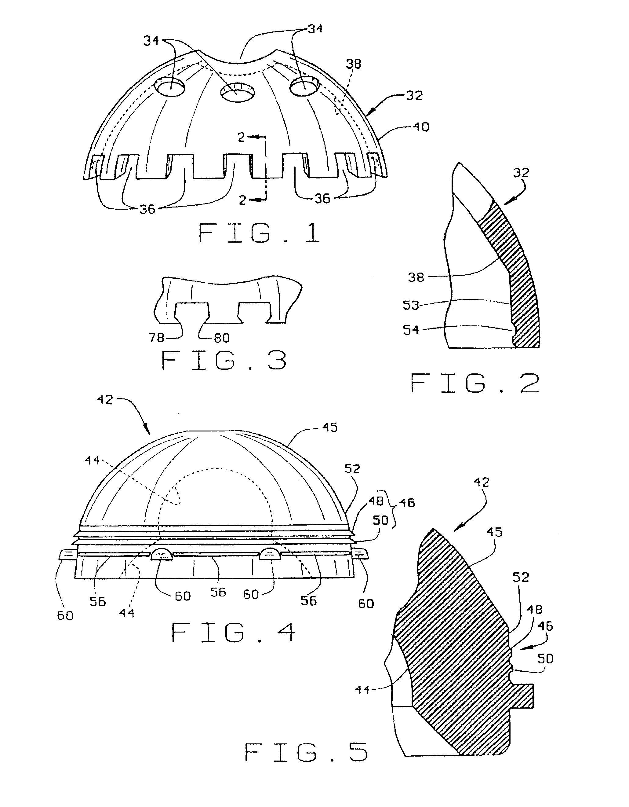
[0019]The prosthesis component of the present invention is an acetabular component for a hip replacement system. FIG. 1 includes an acetabular shell 32 with a plurality of screw holes 34 and a plurality of peripheral notches 36. The acetabular shell 32 has an inner surface 38 and an outer surface 40. The outer surface 40 is generally hemispherical, and is contoured to closely match the shape of a hemispherically reamed acetabular, or cotyloid cavity, into which the shell 32 is to be implanted. The inner surface 38 of the shell 32 is also generally hemispherical, except near its peripheral edge which is relatively flat, and smooth as best seen in FIG. 2.

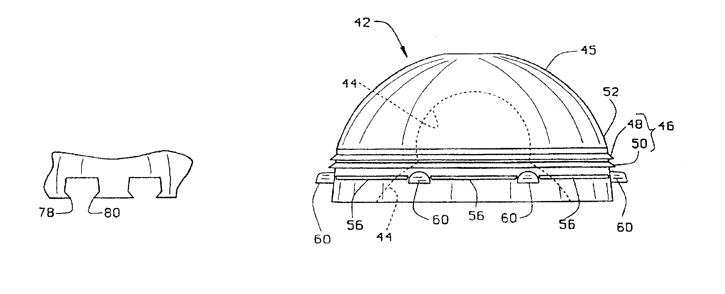
[0020]The liner 42, as shown in FIGS. 4 and 5, is designed to be inserted into the acetabular shell 32. The liner has an inner surface 44 that interfaces with a femoral head component (not shown) of the hip replacement system. The liner is constructed from ultra high molecular weight polyethylene or other similar material, and has an ...


PUM


Abstract

An acetabular component for a hip replacement system comprises an acetabular shell, and a liner having a seal for insertion into the acetabular shell. In the preferred embodiment, the shell has a smooth tapered surface in its peripheral inner surface, and the liner has several annular ridges protruding from its outer surface. Upon insertion of the liner into the shell, the annular ridges of the liner come into sealing engagement with the smooth tapered surface of the shell. This sealing engagement substantially prevents a migration of debris along an interface of the liner with the shell. The liner is provided with several peripheral tabs for interference fit with several peripheral notches in the shell. An interlock comprising another liner ridge and a shell groove, provide a positive engagement to hold the liner in the shell as it bottoms therein. In an alternative embodiment, each notch is provided with protruding lips which project into the notch and firmly grasp one of the tabs of the liner upon insertion of the liner into the shell. In this manner, micromotion between the liner and the shell is substantially inhibited.

Description

[0001]This application is a continuation of application Ser. No. 08 / 466,607 filed on Jun. 6, 1995 now abandoned.This is a reissue of U.S. Pat. No. 5,766,260, issued Jun. 16, 1998, which was based on application Ser. No. 08 / 847,887, filed Apr. 28, 1997, which is a continuation of application Ser. No. 08 / 466,607, filed Jun. 6, 1995, abandoned.BACKGROUND OF THE INVENTION[0002]Prosthesis components for replacing anatomical joints are well known in the art, including total hip replacement systems. These systems include acetabular components and femoral components which interact with the acetabular components to replicate the articulation between the head of a femur and an acetabulum, or cotyloid cavity, of a pelvic girdle. The acetabular component typically comprises two parts, a metal acetabular shell and a polyethylene liner for insertion into the acetabular shell.[0003]Acetabular shells typically have openings in the shell, including screw holes, which give rise to at least two proble...

Claims


Application Information

Patent Timeline
IPC IPC(8): A61F2/32A61F2/00A61F2/30A61F2/34A61F2/46
CPCA61F2/34A61F2002/30378A61F2002/30403A61F2002/30487A61F2002/30589A61F2002/30594A61F2002/30682A61F2002/30879A61F2002/3401A61F2002/3403A61F2002/3435A61F2002/4631A61F2220/0025A61F2220/0033A61F2310/00011A61F2002/3054A61F2002/305
Inventor WHITESIDE, LEO A.
Owner WHITESIDE BIOMECHANICS
Why Eureka
Try Eureka