Multi-cylinder diesel engine with variably actuated valves

a multi-cylinder diesel engine and valve technology, applied in the direction of valve drives, non-mechanical valves, electrical control, etc., can solve the problem that the internal egr can only be realized in a limited measure, and achieve the effect of reducing harmful exhaust emissions, improving performance and/or consumption

Inactive Publication Date: 2008-06-17
CENT RICERCHE FIAT SCPA
View PDF30 Cites 5 Cited by
  • Summary
  • Abstract
  • Description
  • Claims
  • Application Information

AI Technical Summary

Benefits of technology

[0011]The object of the present invention is that of further perfecting the previously proposed engine for the purposes of achieving a series of advantages with regards to reducing harmful exhaust emissions and / or overcoming problems of cold starting or creating the so-called “blue smoke” in the “warm-up” phase after a cold start, and / or achieving improved performance and / or consumption reductions.

Problems solved by technology

In traditional engines, internal EGR can only be realized in a limited measure, as there would otherwise be an excessive reduction in the “swirl” of the air charge introduced into the cylinder due to the introduction of a mass of burnt gases with an angular motion that is null, or low or in the opposite direction.

Method used


Image

  • Multi-cylinder diesel engine with variably actuated valves
  • Multi-cylinder diesel engine with variably actuated valves
  • Multi-cylinder diesel engine with variably actuated valves

Examples


Embodiment Construction

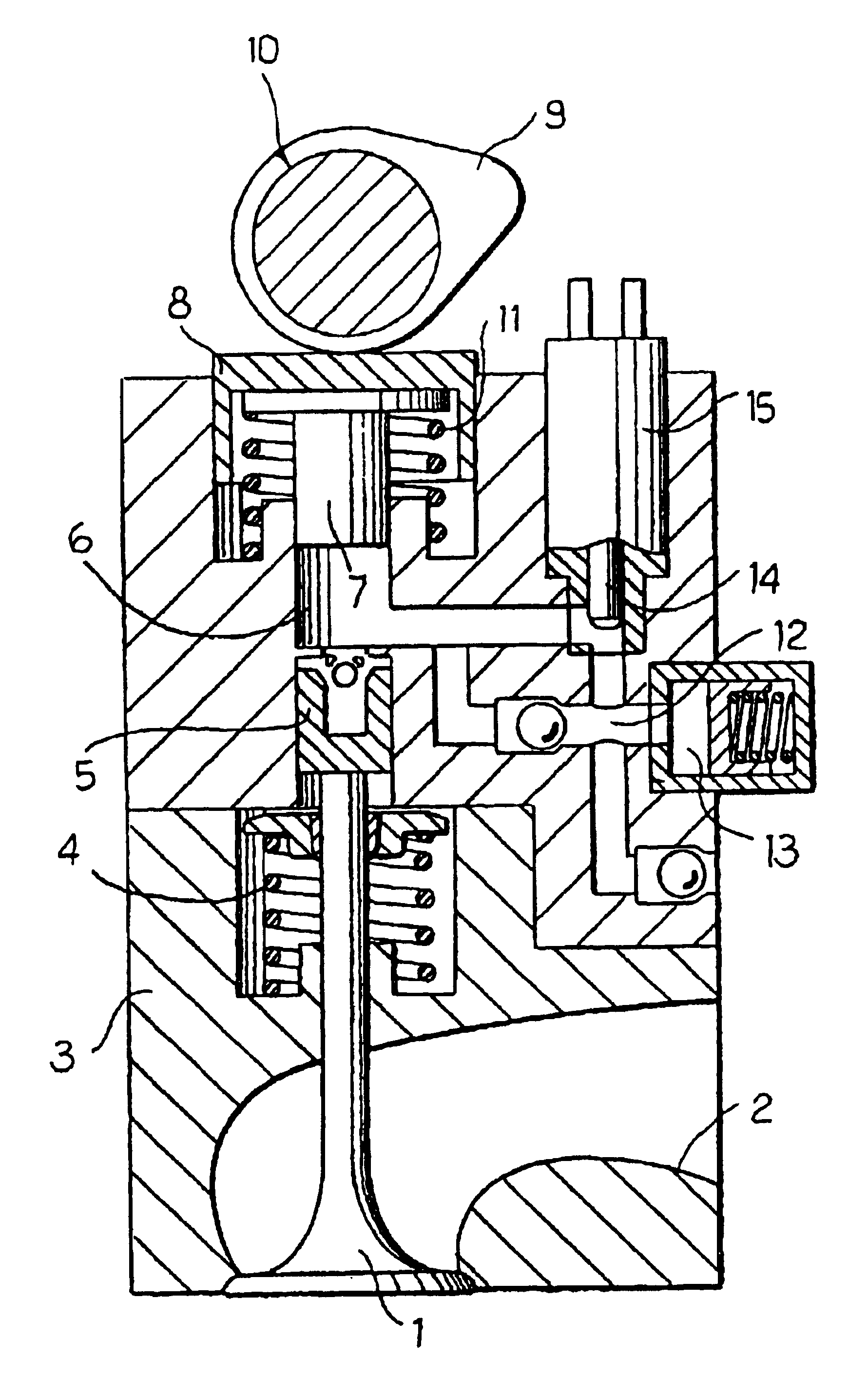
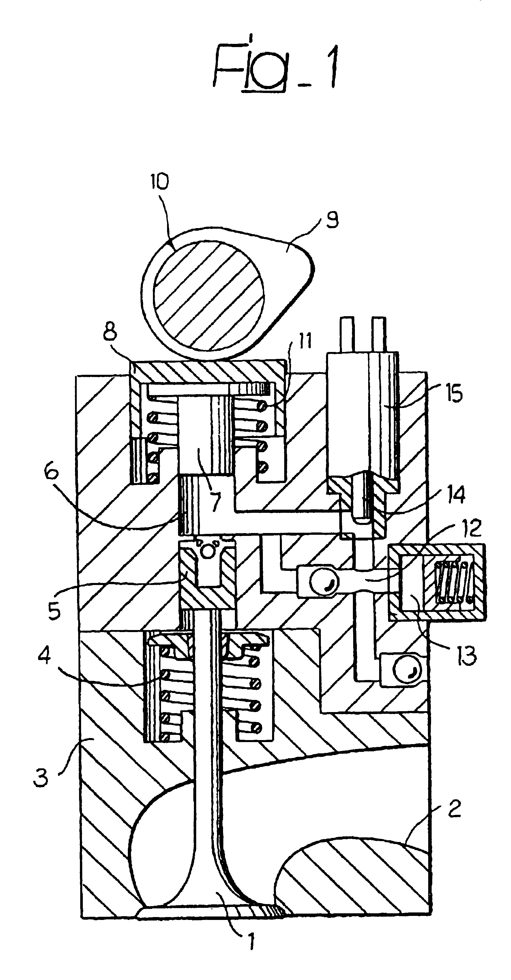
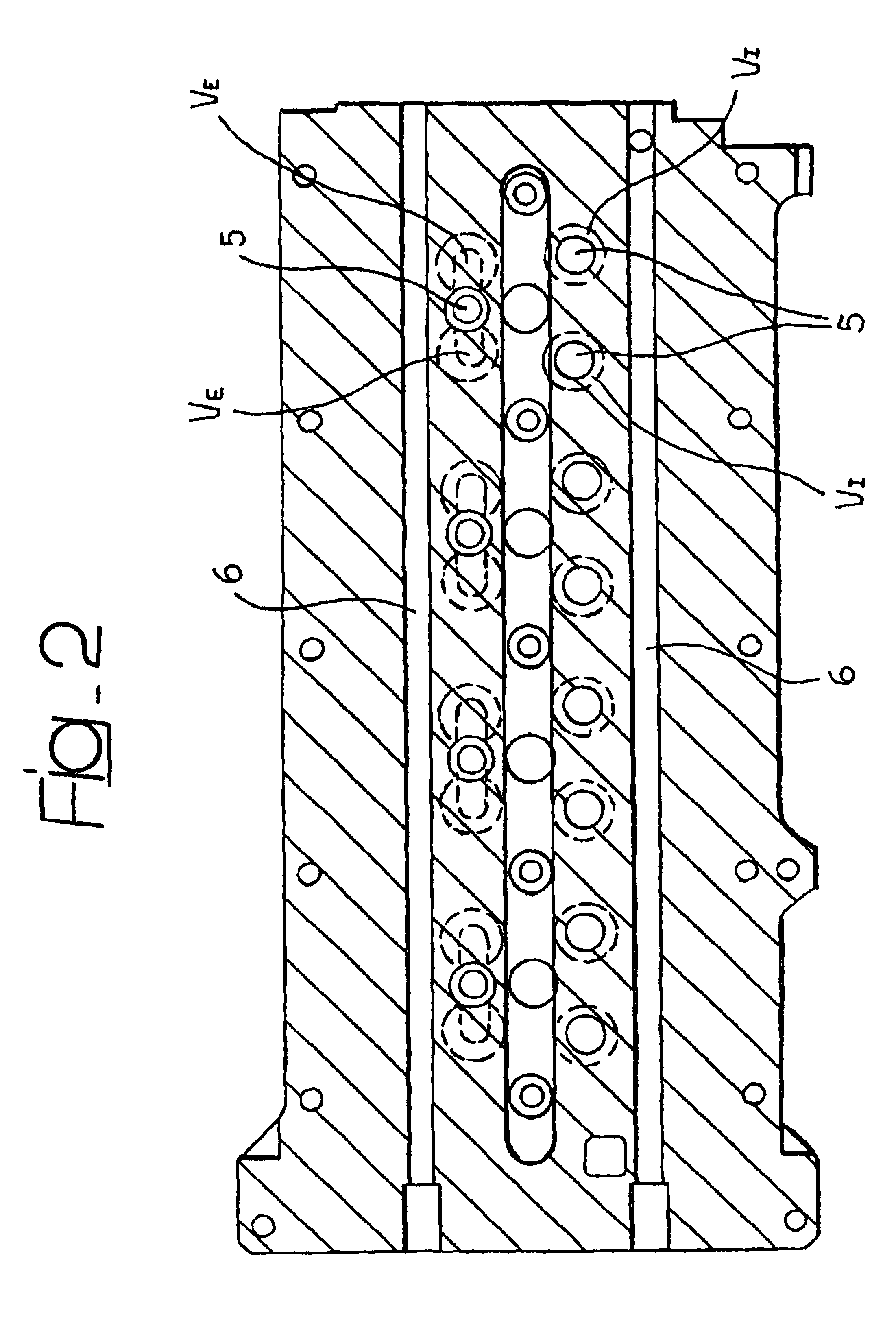
[0031]FIG. 1 schematically illustrates the principle of operation of a variable valve actuation system in an internal combustion engine. Reference number 1 indicates the valve (which can be either an inlet valve or an exhaust valve) as a whole, associated with a respective port 2 (inlet or exhaust) formed inside the cylinder head 3 of an internal combustion engine. The valve 1 is drawn towards its closed position (upwards with reference to FIG. 1) by a spring 4, while it is forced to open by a piston 5 acting on the upper end of the valve stem. The piston 5 is in turn controlled via oil under pressure that is present in the chamber 6, by a piston 7 that supports a spring cup 8 cooperating with a cam 9 on a camshaft 10. The spring cup 8 is held in sliding contact with the cam 9 by a spring 11. The pressure chamber 6 can be connected to a port 12, which in turn communicates with a pressure accumulator 13, via the shutter 14 of a solenoid valve 15 that is commanded by the electronic me...


PUM


Abstract

In a Diesel engine with variably actuated valves, the cam controlling each inlet valve is shaped to provoke the opening of the respective inlet valve during the engine's normal exhaust phase and thus realize exhaust gas recirculation within the engine, due to the fact that during the normal exhaust phase, part of the exhaust gas passes from the cylinder into the inlet port, from where it returns to the cylinder during the next induction phase, while part of the exhaust gas that had previously passed into the exhaust port returns to the cylinder during the induction phase due to the additional opening of the exhaust valve, in consequence of which the exhaust gas charges that return to the cylinder are subjected to further combustion in the next engine cycle.

Description

BACKGROUND OF THE INVENTION[0001]The present invention relates to multi-cylinder Diesel engines of the type employing variably actuated valves.[0002]In American patent U.S. Pat. No. 6,237,551, the Applicant has already proposed an engine of this type including:[0003]two inlet valves and two exhaust valves for each cylinder, each equipped with respective elastic means of return that push the valve towards its closed position, for controlling the respective inlet and exhaust ports,[0004]at least one camshaft for operating the inlet and exhaust valves of the engine's cylinders via respective valve lifters, each inlet valve and the two exhaust valves being controlled by a respective cam of the said camshaft,[0005]in which each of the said valve lifters commands the respective inlet or exhaust valve against the action of the said elastic means of return via the interposition of hydraulic means including a pressurized fluid chamber.[0006]the pressurized fluid chamber associated with each ...

Claims


Application Information

Patent Timeline
Patent Type & Authority Patents(United States)
IPC IPC(8): F02M35/10F01L1/08F01L1/26F01L9/11F01L9/14F01L13/00F01N3/20F01N3/24F02B1/12F02B3/06F02B17/00F02B23/00F02B23/10F02B29/08F02B31/02F02B31/08F02B47/08F02B75/20F02D13/02F02D13/04F02D15/04F02D17/02F02D41/02F02D41/04F02D41/06F02D41/14F02D41/30F02D41/38F02D41/40F02D43/00F02D45/00F02F1/24F02F1/42F02M25/07
CPCF01L1/08F01L1/26F01L1/267F01L13/0005F01L2001/0535F01L2001/0537F01L2001/34446F01L2800/00F02B1/12F02B3/06F02B17/005F02B23/101F02B31/02F02B31/085F02B47/08F02B75/20F02B2275/18F02B2275/20F02B2275/32F02D13/0207F02D13/0253F02D13/0257F02D13/0269F02D13/0273F02D13/0276F02D13/04F02D15/04F02D41/006F02D41/3035F02D2013/0292F02D2041/001F02F1/4214F02F2001/247F02M26/01Y02T10/12Y02T10/40F01L9/14F01L9/11
Inventor GIANOLIO, LAURAMACOR, LORENTINOPECORI, ANDREAVAFIDIS, CONSTANTINOVATTANEO, FRANCESCO
Owner CENT RICERCHE FIAT SCPA
Why Eureka
Try Eureka