Hydrogen-assisted integrated emission control system

a technology of emission control system and hydrogen-assisted technology, which is applied in the direction of exhaust treatment electric control, physical/chemical process catalysts, separation processes, etc., can solve the problems of complex system to handle every aspect of the driving cycle, less effective catalysts used to treat the exhaust of internal combustion engines, and low temperature operation

Active Publication Date: 2021-09-21
BASF CORP
View PDF84 Cites 0 Cited by
  • Summary
  • Abstract
  • Description
  • Claims
  • Application Information

AI Technical Summary

Benefits of technology

[0213]It is clear that the greatest benefit in reduction of harmful exhaust emissions was derived from the H2 pulse in front of the DOC, and the total DOC+SCR system NOx performance improvements, observed from the H2 pulse in front of the DOC, was attributed to either the higher DOC-out temperature, or the increased NO2 concentration after the DOC, or the lower CO / HC concentration after the DOC, or the combination of both temperature and concentrations.

Problems solved by technology

Catalysts used to treat the exhaust of internal combustion engines are less effective during periods of relatively low temperature operation, such as the initial cold-start period of engine operation, because the engine exhaust is not at a temperature sufficiently high for efficient catalytic conversion of noxious components in the exhaust.
In addition, development of emission gas treatment systems for the reduction of NOx (NO and NO2) emissions to nitrogen has become increasingly important, resulting in a more complicated system to handle every aspect of the driving cycles.
However, such systems are expensive and complex, increase back pressure resistance in the exhaust system, and require a significant amount of space in the vehicle to implement.

Method used


Image

  • Hydrogen-assisted integrated emission control system
  • Hydrogen-assisted integrated emission control system
  • Hydrogen-assisted integrated emission control system

Examples


example 1

DOC Article

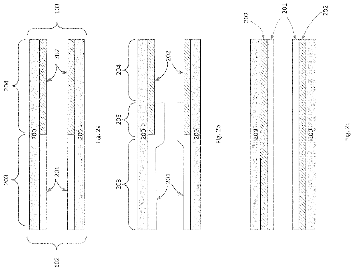
[0182]A bottom coat catalyst slurry containing milled alumina powder impregnated with Pd (0.5 wt. %), Ba (0.8 wt. %) and Pt (0.3 wt. %) is prepared and adjusted to a pH of 4.5 to 5.0 with nitric acid. The bottom coat slurry had a solid content of 38 wt. %. A top coat slurry containing alumina / 5 wt. % Mn and Pt-amine (3.3 wt. %) is prepared, milled and adjusted to a pH of 4.5 to 5.0 with nitric acid. The top coat slurry had a solid concentration of 37 wt. %. Zeolite beta (0.35 g / in3) was added to the top coat slurry.

[0183]The bottom coat slurry was applied to the entire core length of a 1″×3″, 400 cpsi (cells per square inch) honeycomb substrate via a washcoat technique. The coated substrate was air dried at 120° C. and calcined at 500° C. for 1 hour, providing a coating loading of 1.6 g / in3. The top coat slurry was applied over the entire bottom coat and was dried and calcined as the bottom coat, to provide a total coating loading of 2.5 g / in3 and a Pt / Pd weight ratio of ...

example 2

SCRoF Article

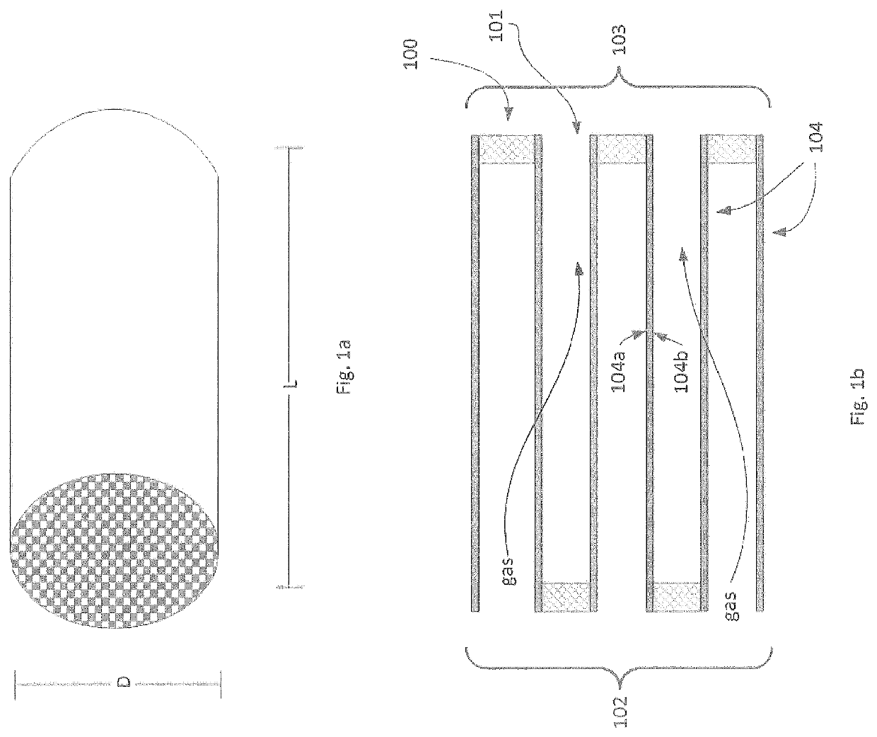
[0184]A catalyst slurry containing milled CuCHA (3.3 wt. % Cu) and 5 wt. % zirconium acetate binder was prepared and applied via a washcoat technique to a 300 / 12, 1″ dia×5.5″ length honeycomb substrate filter with alternate channel openings having a volume of 70.8 cm3. The coated core was dried at 130° C. and calcined at 550° C. for 1 hour to provide a coating loading of 1.75 g / in3.

example 3

Pollution Abatement

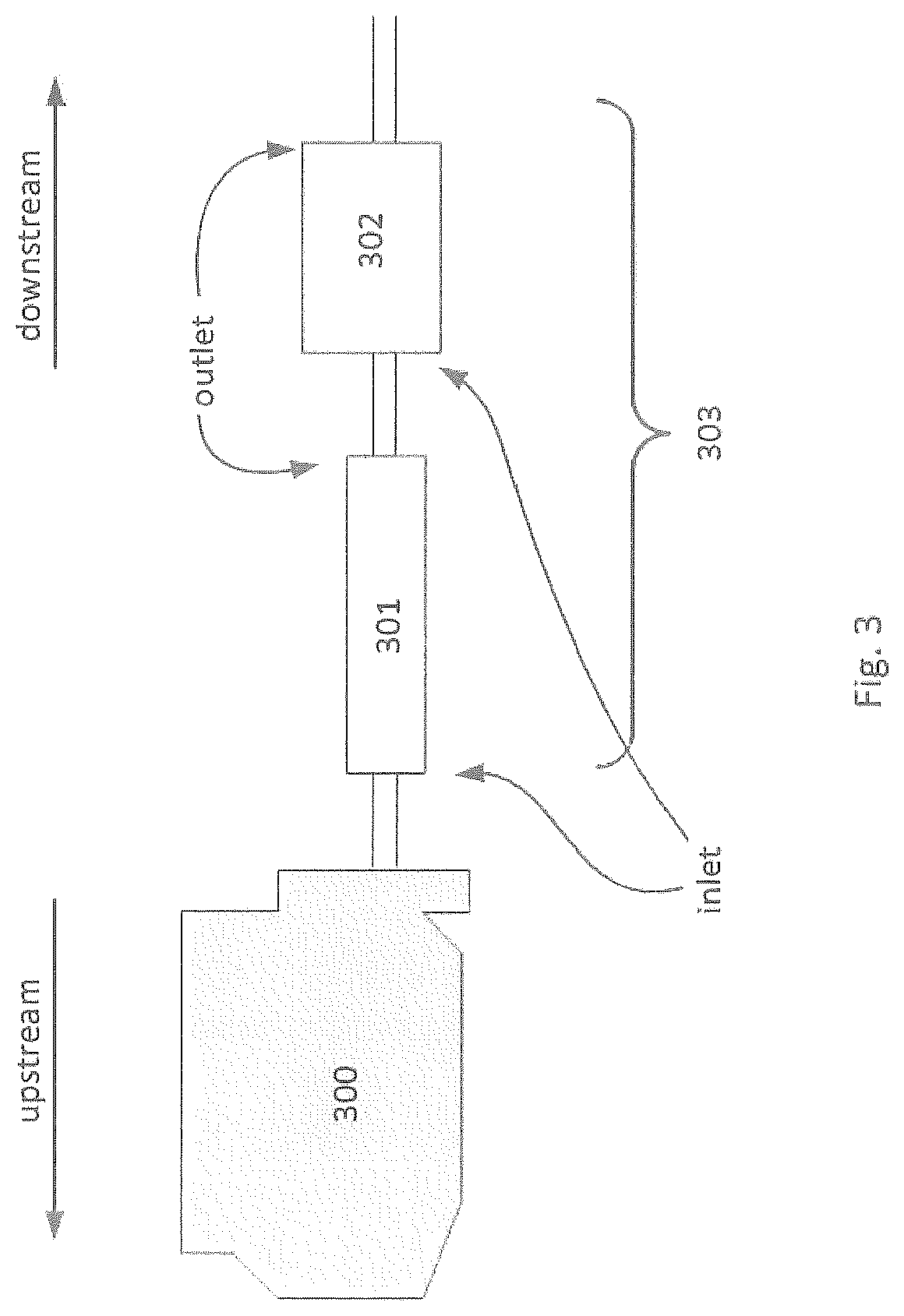
[0185]The coated DOC article of Example 1 is hydrothermally aged in a tube furnace at 800° C. for 16 hours with a feed gas composition of 10% H2O, 10% O2, balance N2. The SCRoF article is fresh. Samples are evaluated in a lab reactor equipped to conduct a simulated NEDC (New European Driving Cycle) with a separate feed line for H2 / N2 serving as the source for H2 pulse, just in front of the DOC. NH3 was injected prior to SCRoF at NH3 / NOx ratio=1 on a second-by-second basis. Engine out temperature traces between vehicle and simulator are provided in FIG. 5, and engine out CO emissions between the vehicle trace and simulator are provided in FIG. 6. Hydrogen injection impact was evaluated for the DOC only and for the DOC+SCRoF system, with a sampling line taken between the DOC and SCRoF, as well as a second sampling line after the combined system. The SCRoF article was downstream of the DOC article.

[0186]Hydrogen was pulsed into the exhaust stream during the first 200...


PUM

PropertyMeasurementUnit
porosityaaaaaaaaaa
pore sizeaaaaaaaaaa
exhaust temperaturesaaaaaaaaaa

Abstract

The invention provides an emission control system for treatment of an exhaust gas stream that includes an oxidation catalyst composition disposed on a substrate in fluid communication with the exhaust gas stream; at least one selective catalytic reduction (SCR) composition disposed on a substrate downstream from the oxidation catalyst composition, and a hydrogen injection article configured to introduce hydrogen into the exhaust gas stream upstream of the oxidation catalyst composition or downstream of the oxidation catalyst composition and upstream of the at least one SCR composition. The invention also provides a method of treating an exhaust gas stream, the method including receiving the exhaust gas stream into the emission control system of the invention and intermittently introducing hydrogen upstream of the oxidation catalyst article or downstream of the oxidation catalyst article and upstream stream of the SCR article.

Description

CROSS-REFERENCE TO RELATED APPLICATIONS[0001]This application is a 35 U.S.C. § 371 application of International Application No. PCT / US2018 / 052305, filed Apr. 3, 2018, which International Application was published by the International Bureau in English on Oct. 11, 2018, and claims priority to U.S. Provisional Application No. 62 / 481,406, filed Apr. 4, 2017, which are incorporated herein by reference in their entirety and for all purposes.FIELD OF THE INVENTION[0002]The invention relates generally to the field of selective catalytic reduction catalysts and oxidation catalysts, as well as emission control systems employing such catalysts.BACKGROUND OF THE INVENTION[0003]Environmental regulations for emissions of internal combustion engines are becoming increasingly stringent throughout the world. Operations of lean burn engines, for example diesel engines, provide the user with excellent fuel economy due to their operation at high air / fuel ratios under fuel lean conditions. However, die...

Claims


Application Information

Patent Timeline
Patent Type & Authority Patents(United States)
IPC IPC(8): F01N3/08F01N3/10F01N3/20F01N3/28B01J21/04B01J23/58B01J23/656B01J29/76B01J35/00B01J35/04B01D53/94
CPCF01N3/2066B01D53/944B01D53/9418B01D53/9472B01D53/9477B01J21/04B01J23/58B01J23/6562B01J29/763B01J35/0006B01J35/04F01N3/0835F01N3/103F01N3/2825B01D2255/1021B01D2255/1023B01D2255/1025B01D2255/2042B01D2255/2073B01D2255/20715B01D2255/20761B01D2255/50B01D2255/904B01D2255/9032B01D2255/911B01D2255/9155B01D2255/9202B01D2255/9205F01N2330/02F01N2330/06F01N2330/30F01N2370/04F01N2610/04F01N2610/1453F01N3/2828F01N3/035F01N2510/0682F01N13/009F01N2370/02Y02T10/12F01N9/00F01N3/106
Inventor SUNG, SHIANGNEUBAUER, TORSTENPATWARDHAN, PUSHKARAJ R.STIEBELS, SUSANNEZABEL, CLAUDIA
Owner BASF CORP
Why Eureka
Try Eureka