Digital battery

a digital battery and battery technology, applied in the field of batteries, to achieve the effects of reducing battery and cell production costs, increasing electrical and physical flexibility, and improving battery reliability and efficiency

Inactive Publication Date: 2009-03-17
MB RES & DEV LLC A CA ITD LIABILITY
View PDF37 Cites 18 Cited by
  • Summary
  • Abstract
  • Description
  • Claims
  • Application Information

AI Technical Summary

Benefits of technology

[0023]A dynamic battery array of the present invention provides increased electrical and physical flexibility, with substantial improvement in battery reliability and efficiency combined with decreased battery and cell production cost. In general, the cost of the product into which the battery array is placed is further reduced in addition to the savings gained from a decrease in battery cost.
[0024]A dynamic battery array of the present invention employs low resistance switch arrays for dynamically and instantaneously forming individual power networks or power buses between selected power cells and individual electrical loads in electrical circuits. The low resistance switch arrays (generally less than approximately 0.5, and preferably less than approximately 0.01 ohms of ON resistance per switch) in such dynamic battery arrays are, for example, semiconductor switches, controlled, for example, by a central processor unit (CPU). Preferably several switches are associated with each cell so as to provide the maximum possible electrical flexibility. The operation of the array is preferably programmable. The term “switch array” is intended to include the switches, the switch and circuit control elements such as a CPU, memory of all types, thermal and other sensors, associated elements, and the like. The circuits to which such battery arrays are applied are generally complex circuits in which several different loads occur, each of which has a different power requirement. Such battery arrays are also applicable to single load circuits where the power requirements fluctuate or the maintenance of a precise power level is required for the duration of the charge cycle of the battery array. If a considerable excess of cells is provided, individualdiscrete cells in the array can be swapped in and out to maintain desired power levels during, for example, start-up, or near the end of a charge cycle.

Problems solved by technology

The circuits to which such battery arrays are applied are generally complex circuits in which several different loads occur, each of which has a different power requirement.

Method used


Image

  • Digital battery
  • Digital battery
  • Digital battery

Examples


Embodiment Construction

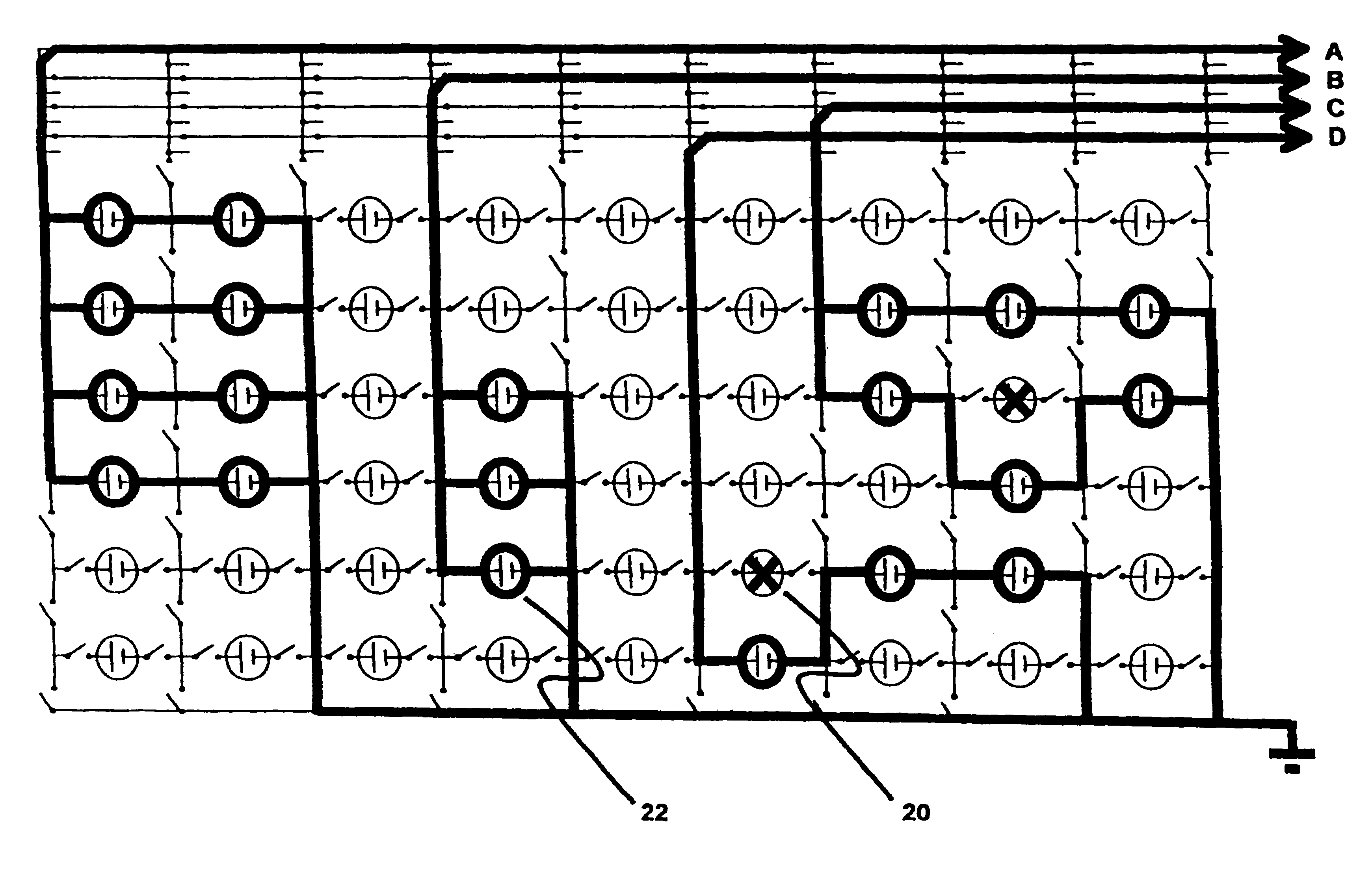
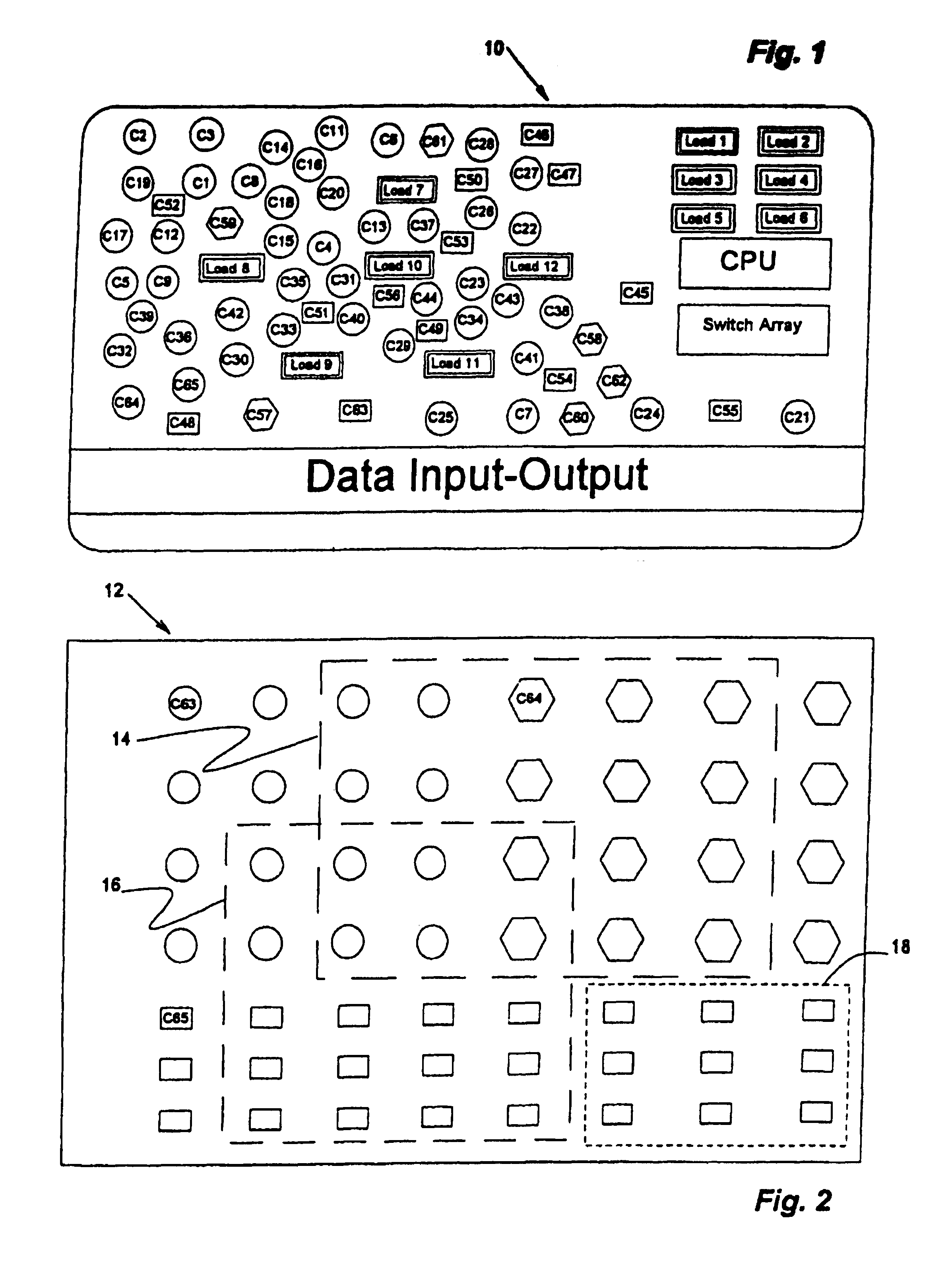
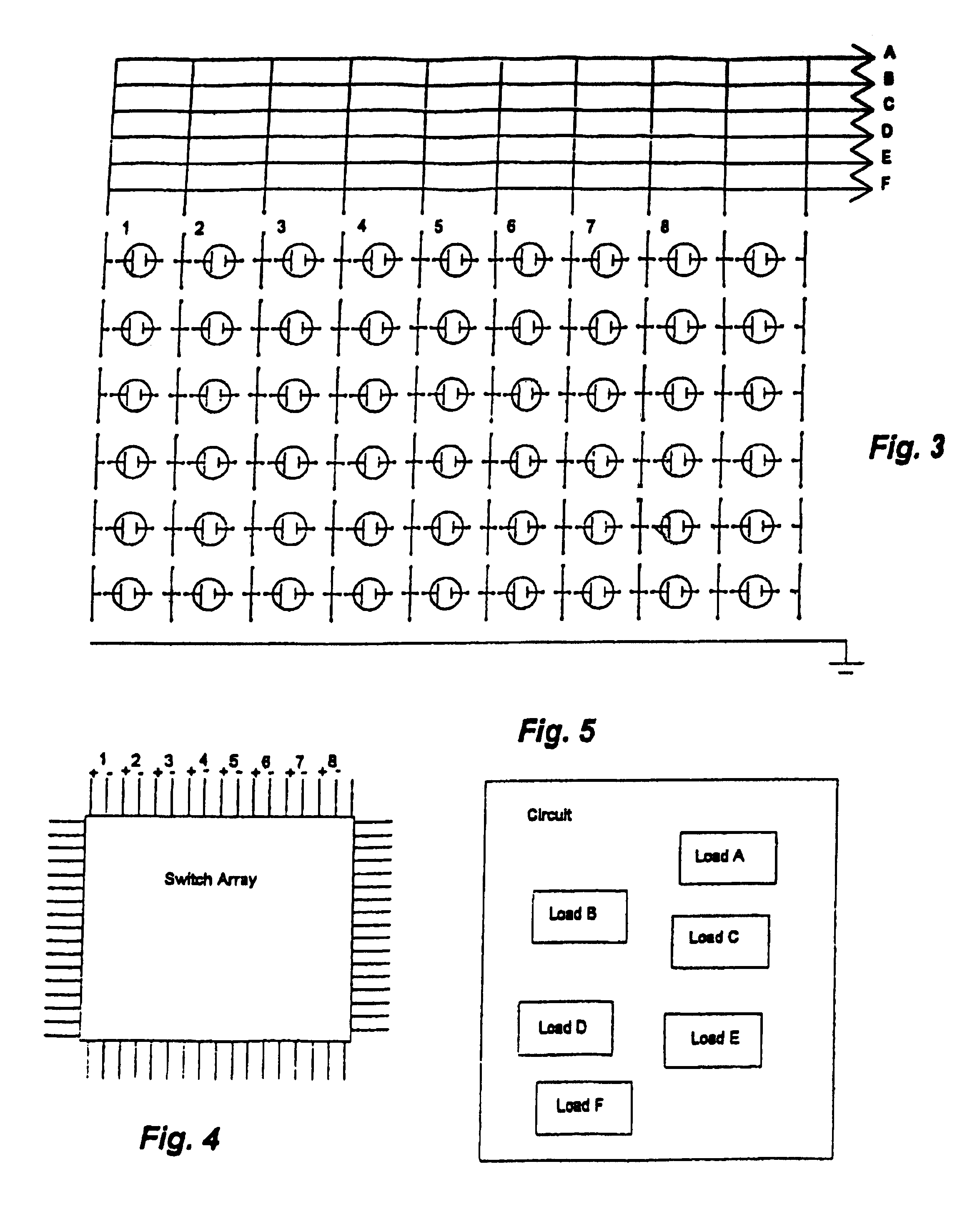
[0034]Referring now to the drawings wherein like reference numerals designate identical or corresponding parts throughout the several views, there is illustrated generally at 10 in FIG. 1 a battery array according to the present invention applied to a conventional credit card. For reasons of clarity of illustration, the electrical leads are not shown. Twelve different electrical loads, Load 1 through Load 12, are illustrated, as are 62 different power cells, C1 through C62, respectively. A semiconductor switch array, for example, a gate array and a central processor unit (CPU) are diagrammatically indicated. Preferably, the CPU is physically integrated into the switch array.

[0035]The credit card is in the form of a circuit board, and the cells in the battery array are preferably formed in pockets or through holes in the printed circuit board, as are the switch array, CPU, and the respective Loads. Preferably, the various components do not project out of the plane of the opposed exte...


PUM

PropertyMeasurementUnit
ON resistanceaaaaaaaaaa
voltageaaaaaaaaaa
voltageaaaaaaaaaa

Abstract

A dynamic battery array of individualdiscrete cells, controllably interconnected for instantaneous dynamic configuration into a plurality of individual power buses having different electrical power output characteristics, each of which is tailored to supply the electrical power required at the instant by a particular electrical load within a circuit. Preferably the cells are fungible and randomly available so that at any given instant any given cell can be poweringly associated with a particular electrical load. The dynamic battery array, consisting of discrete cells lends itself to mounting on physically flexible substrates such as credit cards. The programmable array employs low resistance switch arrays for dynamically and instantaneously forming individual power networks or power buses between selected power cells and individual electrical loads in electrical circuits. The circuits to which such battery arrays are applied are generally complex circuits in which several different loads occur, each of which has a different power requirement.

Description

RELATED APPLICATIONS[0001]TheThis application is a Reissue Application of U.S. Ser. No. 10 / 269,802, filed Oct. 11, 2002, now U.S. Pat. No. 6,731,022, granted May 4, 2004, for which the benefit of Provisional Application Serial No. 60 / 329,459, filed Oct. 11, 2001 is claimed.BACKGROUND OF THE INVENTION[0002]1. Field of the Invention[0003]The invention relates in general to battery arrays, and, in particular, to self healing dynamically configurable battery arrays that are capable of forming a plurality instantaneous power buses, each of which is configured to the electrical power requirements of specific components or modules (loads) of an electrical circuit, sometimes referred to herein as a “digital battery” or a “dynamic battery array”.[0004]2. Description of the Prior Art[0005]Electronic devices are becoming more and more complex. Such complex electronic devices typically contain a plurality of different components or modules (loads), each of which has its own unique voltage and c...

Claims


Application Information

Patent Timeline
Patent Type & Authority Patents(United States)
IPC IPC(8): H02J7/34H01M10/44H01M6/40H01M6/50H01M10/04H01M10/42H01M50/50H02J7/00
CPCH01M6/40H01M6/5016H01M10/0436H01M10/4207H01M10/425H01M10/4257H01M10/44Y02E60/10H01M50/50H02J7/0013H02J7/005Y02P70/50H02J7/00
Inventor SILVERMAN, MARTIN S.
Owner MB RES & DEV LLC A CA ITD LIABILITY
Why Eureka
Try Eureka