[0010]A first
advantage of the present invention is that it crushes leaves, sticks, pine
straw, pinecones and related debris on lawns, yards, and fields. Yet another
advantage of the present invention is that it has unlimited capacity because it continuously bales and eliminates leaves. In such context, the present invention produces bales that can be conveniently lifted and carried.
[0011]Still another
advantage of the present invention is that it automatically gathers leaves thereby avoiding raking. Further, another advantage of the present invention is that it is hydraulically driven. Still further, another advantage of the present invention is that it does not have augers which require a housing.
[0012]Another advantage of the present invention is that it is removably attachable to a
prime mover. Finally, another advantage of the present invention is that can be used without the compactor and baler to produce
mulch.
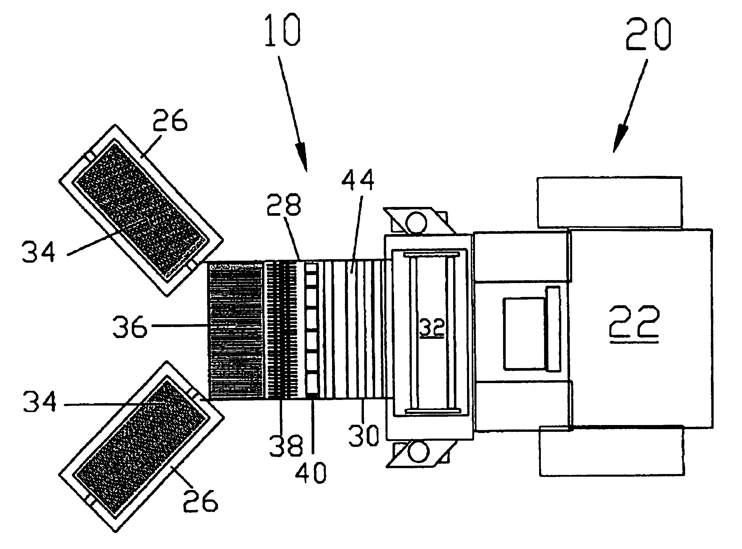
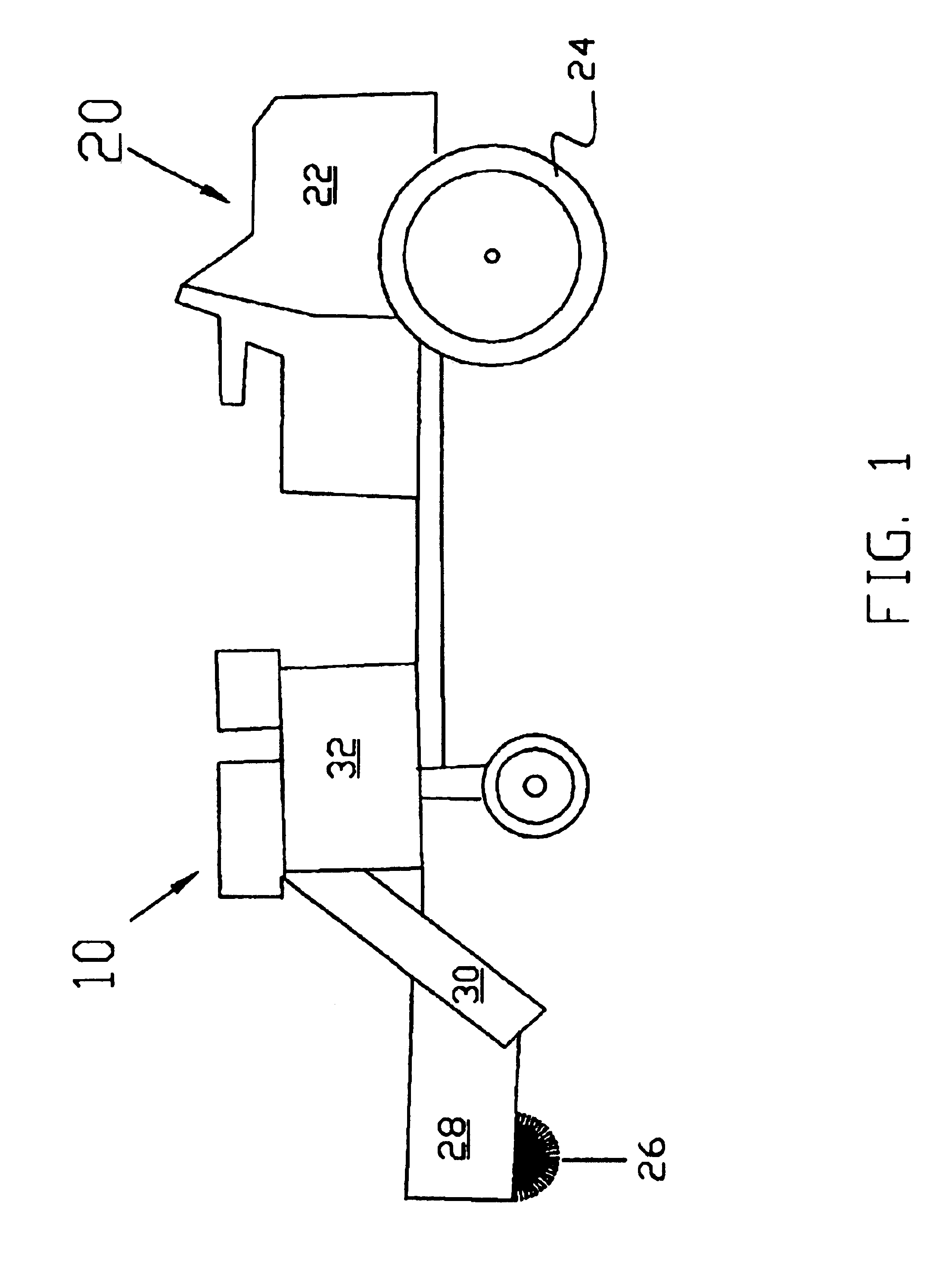
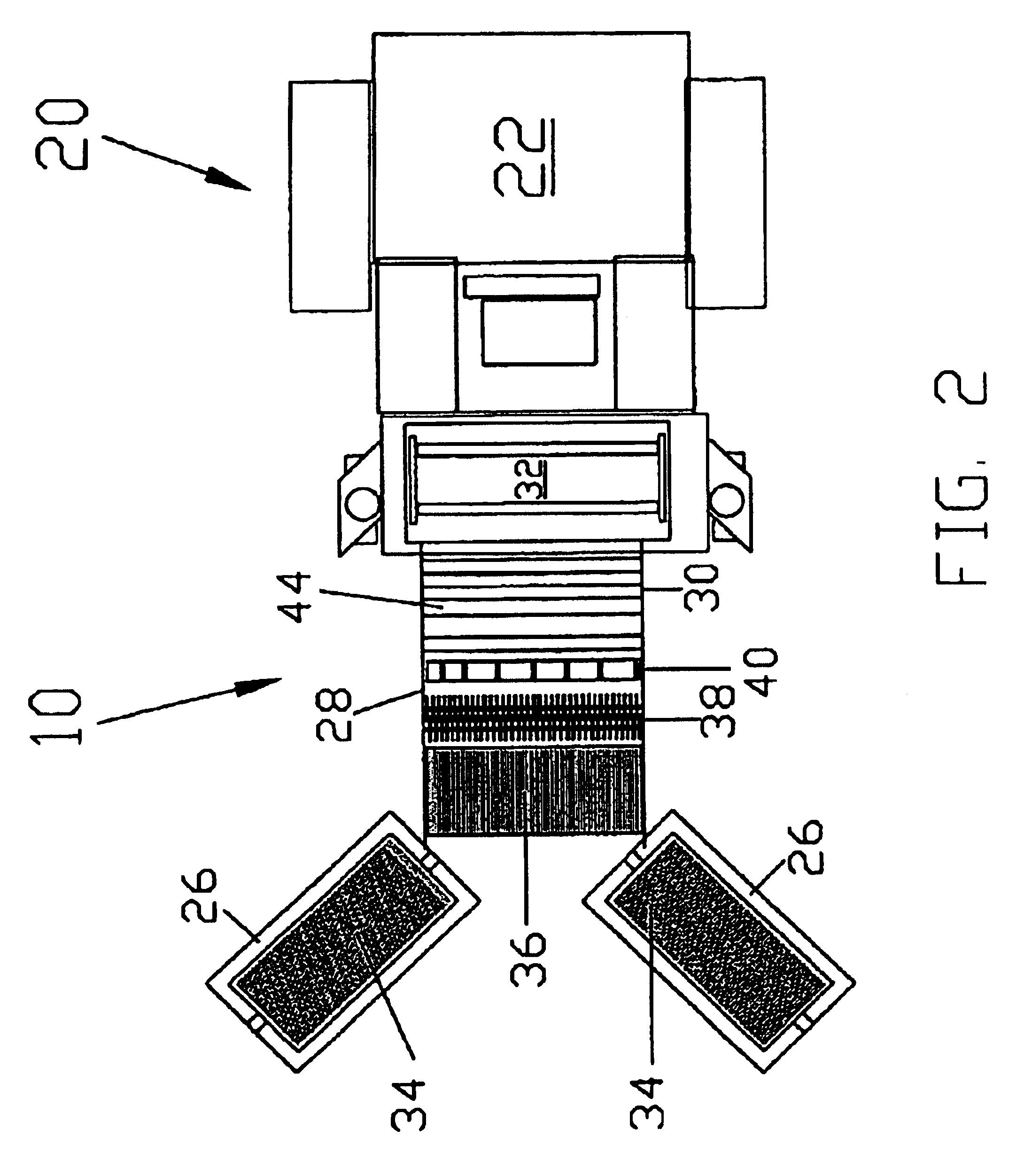
[0013]In one exemplary embodiment, there may be provided a gathering and baling apparatus capable of crushing sticks and similar material associated with the leaves. The apparatus is reversibly attached to a
prime mover that can move the apparatus across lawns and fields as needed. In a first embodiment of the present invention, the front portion of the apparatus may have brushes extending diagonally at an angle to the centerline of the apparatus. The brushes roll inwardly on their bottom edges to gather leaves towards the front of the apparatus. The roller brushes direct and lift the leaves to a crusher. The crusher has one or more pairs of crushing rollers. Each crushing roller in a pair has crushing vanes and the crushing vane of one crushing roller inter-digitate or meshes with the crushing vane of the other crushing roller. The crushing rollers are driven by a motor to rotate towards one another so that the leaves and sticks and related debris from the brushes will be fed into the crushing roller pair and be crushed by the crushing vanes as the crushing rollers rotate. Crushed material can pass through one or more additional pairs of like crushing rollers, but will eventually fall and be pushed to the bottom of the crusher where it will be forced out of the crusher by a similar pair of crushing rollers with crushing vanes and be deposited onto a conveyor mechanism. The conveyor mechanism moves the crushed debris to a baler
assembly. The baler
assembly has two compacting rollers contained within a continuous band. One of the baler
assembly compacting rollers is fixed and the other compacting roller is movable. When the movable compacting roller is moved away from the fixed compacting roller, the band can receive the crushed debris from the conveyor mechanism. Once the crushed debris is deposited on the band, the adjustable compacting roller is moved toward the fixed compacting roller, thereby compressing the debris further. The compacting rollers are rotated in the same direction by motors, causing the crushed compressed debris to rotate within the band. As the crushed debris rotates within the band, baling material such as paper is inserted between the compacting rollers and is directed by the moving band around the rotating debris. The paper tightly encircles the rotating debris, thus baling it. The movable roller within the compactor is moved away from the fixed roller, the baler assembly is rotated, and the baled debris is expelled. This sequence of gathering, crushing, conveying, compacting, and baling debris is produced continuously and automatically as the apparatus moves forward gathering leaves.
[0014]In a second exemplary embodiment of the present invention, the front portion of the apparatus may be brushes extending diagonally at an angle to the centerline of the apparatus. The brushes roll inwardly on their bottom edges to gather leaves towards the front of the apparatus. The roller brushes direct and lift the leaves to a conveyor mechanism. The conveyor mechanism moves the crushed debris to a crusher. The crusher has one or more pairs of crushing rollers. Each crushing roller in a pair has crushing vanes and the crushing vane of one crushing roller inter-digitate or meshes with the crushing vane of the other crushing roller. The crushing rollers are driven by a motor to rotate towards one another so that the leaves and sticks and related debris from the brushes will be fed into the crushing roller pair and be crushed by the crushing vanes as the crushing rollers rotate. Crushed material can pass through one or more additional pairs of like crushing rollers, but will eventually fall and be pushed to the bottom of the crusher where it will be forced out of the crusher by a similar pair of crushing rollers with crushing vanes and be deposited into a baler assembly. The baler assembly has two compacting rollers contained within a continuous band. One of the baler assembly compacting rollers is fixed and the other compacting roller is movable. When the movable compacting roller is moved away from the fixed compacting roller, the band can receive the crushed debris from the conveyor mechanism. Once the crushed debris is deposited on the band, the adjustable compacting roller is moved toward the fixed compacting roller, thereby compressing the debris further. The compacting rollers are rotated in the same direction by motors, causing the crushed compressed debris to rotate within the band. As the crushed debris rotates within the band, baling material, such as paper is inserted between the compacting rollers and is directed by the moving band around the rotating debris. The paper tightly encircles the rotating debris, thus baling it. The movable roller within the compactor is moved away from the fixed roller, the baler assembly is rotated, and the baled debris is expelled. This sequence of gathering, conveying, crushing, compacting, and baling debris is produced continuously and automatically as the apparatus moves forward gathering leaves.
[0015]In a third exemplary embodiment of the present invention, the apparatus is attached to a prime mover, such as a
lawn mower base. Unlike the other alternative embodiments, the present embodiment lacks brushes extending diagonally at an angle to the centerline of the apparatus for the collection of debris. In the present embodiment, debris is manually introduced by the operator into the crusher. The crusher has one or more pairs of crushing rollers. Each crushing roller in a pair has crushing vanes and the crushing vane of one crushing roller interdigitate or meshes with the crushing vane of the other crushing roller. The crushing rollers are driven by a motor to rotate towards one another so that the leaves and sticks and related debris from the brushes will be fed into the crushing roller pair and be crushed by the crushing vanes as the crushing rollers rotate. Crushed material can pass through one or more additional pairs of like crushing rollers, but will eventually fall and be pushed to the bottom of the crusher where it will be forced out of the crusher by a similar pair of crushing rollers with crushing vanes and be deposited into a baler assembly. The baler assembly has two compacting rollers contained within a continuous band. One of the baler assembly compacting rollers is fixed and the other compacting roller is movable. When the movable compacting roller is moved away from the fixed compacting roller, the band can receive the crushed debris from the conveyor mechanism. Once the crushed debris is deposited on the band, the adjustable compacting roller is moved toward the fixed compacting roller, thereby compressing the debris further. The compacting rollers are rotated in the same direction by motors, causing the crushed compressed debris to rotate within the band. As the crushed debris rotates within the band, baling material, such as paper is inserted between the compacting rollers and is directed by the moving band around the rotating debris. The paper tightly encircles the rotating debris, thus baling it. The movable roller within the compactor is moved away from the fixed roller, the baler assembly is rotated, and the baled debris is expelled. The crushing, compacting, and baling sequence is guided by the user during the operation of the apparatus. The present embodiment is significantly smaller in size than the alternative embodiments and while motor driven is primarily manual in its
continuous operation.

