
Fluid gauge proximity sensor and method of operating same using a modulated fluid flow

a technology of proximity sensor and fluid flow, which is applied in the direction of measuring devices, instruments, using fluid means, etc., can solve the problems of significant deformation or ruination of workpieces, serious shortcomings of sensors, and significant challenges associated with creating proximity sensors of such accuracy

Active Publication Date: 2011-08-30
ASML HLDG NV
View PDF56 Cites 0 Cited by
  • Summary
  • Abstract
  • Description
  • Claims
  • Application Information

AI Technical Summary

Benefits of technology

This solution provides accurate nanometer-level distance measurement, reduces contamination risks, and is insensitive to external noise and material properties, allowing for precise proximity sensing in various lithography environments without the need for specific fluid conditioning.

Problems solved by technology

The challenges associated with creating a proximity sensor of such accuracy are significant, particularly in the context of lithography systems.
Occurrence of either situation may significantly degrade or ruin the work piece.
These proximity sensors have serious shortcomings when used in lithography systems because physical properties of materials deposited on wafers or substrates may impact the precision of these devices.
For example, capacitance gauges, being dependent on the concentration of electric charges, can yield spurious proximity readings in locations where one type of material (e.g., metal) is concentrated.
Another class of problems occurs when exotic wafers made of non-conductive and / or photosensitive materials, such as Gallium Arsenide (GaAs) and Indium Phosphide (InP), are used.
Further problems can results from light interacting with under-the-surface parts of wafers or substrates, which can cause spurious reflections and unwanted interference patterns.
In these cases, capacitance and optical sensors are not optimal.
One issue with fluid gauge proximity sensors is that they require a steady flow of a fluid, which leads to issues of contamination and thermal conditioning.
They also are sensitive to low frequency external acoustical interference and sensor offset errors.

Method used


Image

  • Fluid gauge proximity sensor and method of operating same using a modulated fluid flow
  • Fluid gauge proximity sensor and method of operating same using a modulated fluid flow
  • Fluid gauge proximity sensor and method of operating same using a modulated fluid flow

Examples


Embodiment Construction

Overview

[0024]While the present invention is described herein with reference to illustrative embodiments for particular applications, it should be understood that the invention is not limited thereto. Those skilled in the art with access to the teachings provided herein will recognize additional modifications, applications, and embodiments within the scope thereof and additional fields in which the present invention would be of significant utility.

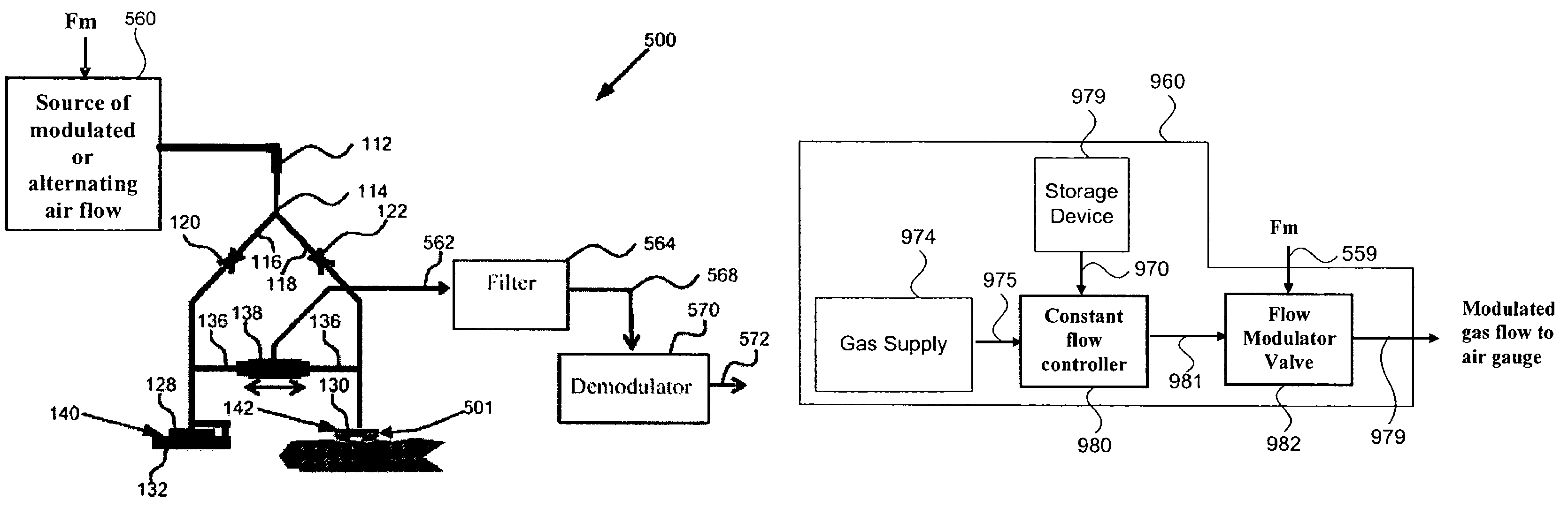
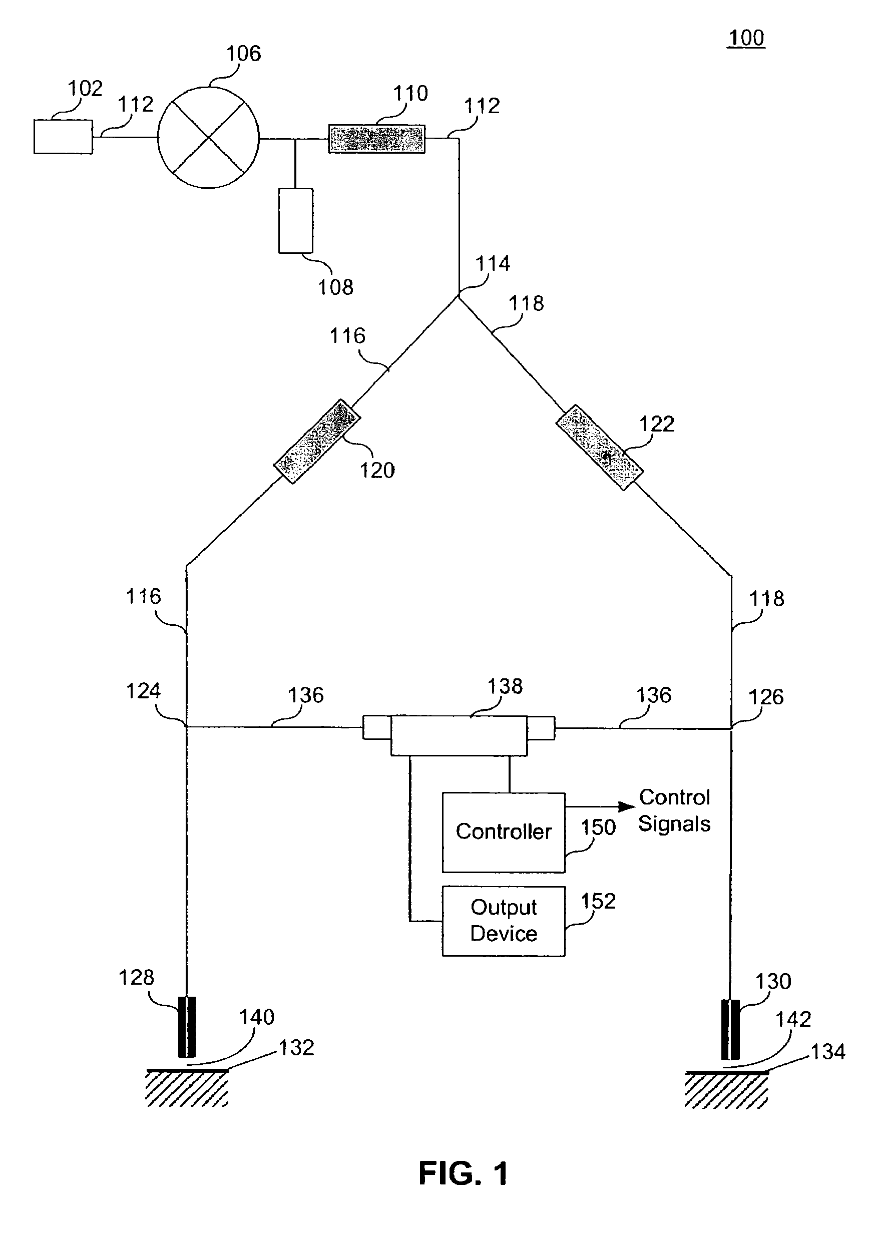
[0025]An embodiment of the present invention provides a system and method that use a fluid gauge proximity sensor. A source of modulated unidirectional or alternating fluid flow travels along at least one path having a nozzle and a flow or pressure sensor. The fluid exists at a gap between the nozzle and a target. The sensor outputs an amplitude modulated signal that varies according to a size of the gap.

[0026]In one example, modulated fluid interacts with only a target (e.g., a measurement surface), while in another example, the modulated...


PUM


Abstract

A system and method that use a fluid gauge proximity sensor. A source of modulated unidirectional or alternating fluid flow travels along at least one path having a nozzle and a flow or pressure sensor. The fluid exists at a gap between the nozzle and a target. The sensor outputs an amplitude modulated signal that varies according to a size of the gap. The amplitude modulated signal is processed either digitally or in analog devices, which can include being filtered (e.g., band pass, band limited, high pass, etc. filter) to include the modulated frequency and sufficient bandwidth on either side of that frequency and / or being demodulated using a demodulator operating at the acoustical driver modulation frequency. Using this system and method can result in only ambient acoustical energy in a desired frequency range of the device actually having the opportunity to interfere with the device operation. This can lower the devices overall sensitivity to external acoustical noise and sensor offset.

Description

BACKGROUND OF THE INVENTION[0001]1. Field of the Invention[0002]The present invention relates to an apparatus and method for detecting very small distances, and more particularly to proximity sensing with fluid flow.[0003]2. Related Art[0004]Many automated manufacturing processes require the sensing of the distance between a manufacturing tool and a product or material surface being worked, often referred to as the “work piece” (e.g., a semiconductor wafer, a flat panel display substrate, or the like). In some situations, such as lithography (e.g., maskless lithography, immersion lithography, photolithography, etc), the distance must be measured with accuracy approaching a nanometer.[0005]The challenges associated with creating a proximity sensor of such accuracy are significant, particularly in the context of lithography systems. In the lithography context, in addition to being non-intrusive and having the ability to precisely detect very small distances (e.g., in the nanometer ran...

Claims


Application Information

Patent Timeline
Patent Type & Authority Patents(United States)
IPC IPC(8): G01B13/08
CPCG01B13/04
Inventor GALBURT, DANIEL N.EBERT, EARL W.LYONS, JOSEPH H.
Owner ASML HLDG NV
Features
  • Generate Ideas
  • Intellectual Property
  • Life Sciences
  • Materials
  • Tech Scout
  • Unparalleled Data Quality
  • Higher Quality Content
  • 60% Fewer Hallucinations
Learn More