
Clamping device for a cutting insert

a technology of cutting inserts and clamping devices, which is applied in the direction of cutting inserts, manufacturing tools, shaping cutters, etc., can solve the problems of blade jaw wear, key wear, and frictional wear of the jaw and/or the key, so as to avoid or minimize damage, avoid frictional wear of the surface, and prolong the life of the holder blade

Inactive Publication Date: 2012-07-24
ISCAR LTD
View PDF18 Cites 4 Cited by
  • Summary
  • Abstract
  • Description
  • Claims
  • Application Information

AI Technical Summary

Benefits of technology

[0004]It is an object of the present invention to provide a new and improved metal cutting tool assembly in which the above-referred-to disadvantages are substantially reduced or overcome.
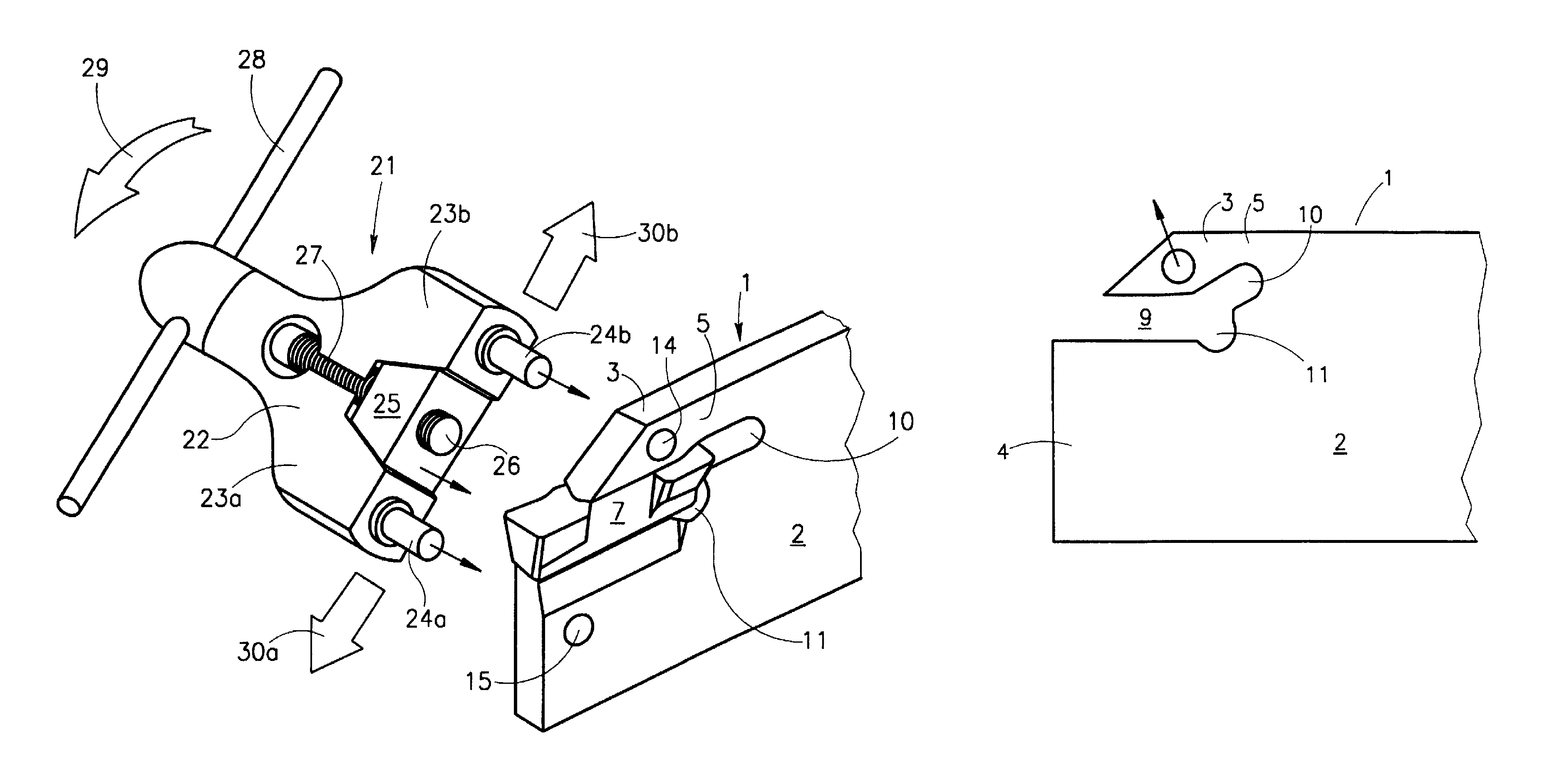
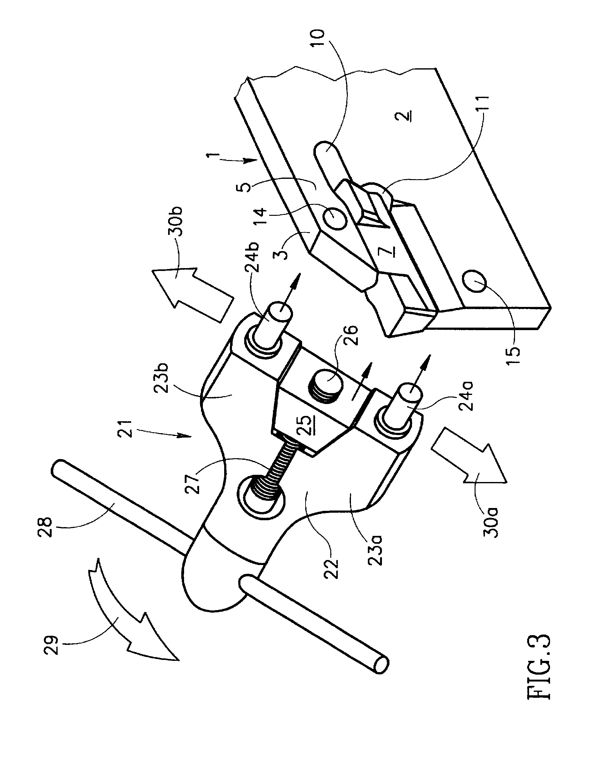
[0009]Thus, with a cutting tool assembly in accordance with the present invention, displacement of the clamping jaw, whether effected by a levering action or by way of a direct, linearly directed displacement, is not accompanied by any direct contact, either with the insert or with the inner surface of the clamping jaw, and in this way damage thereto is avoided or minimized. Furthermore, introduction into and removal of the insert from the slot is not accompanied by any frictional resistance by the opposite jaw surfaces and there is therefore avoided frictional wear of these surfaces leading to an extended life of the holder blade as a whole.

Problems solved by technology

It will be understood that both the insertion and removal of the insert is accompanied by significant friction with consequent wear on the blade jaws which are, in general, of a much softer material than that of the insert.
The outward displacement of the jaw is effected using a mechanical key which is displaced in frictional contact with the inside of the clamping jaw, thereby leading to frictional wear of the jaw and / or the key.

Method used


Image

  • Clamping device for a cutting insert
  • Clamping device for a cutting insert
  • Clamping device for a cutting insert

Examples


Embodiment Construction

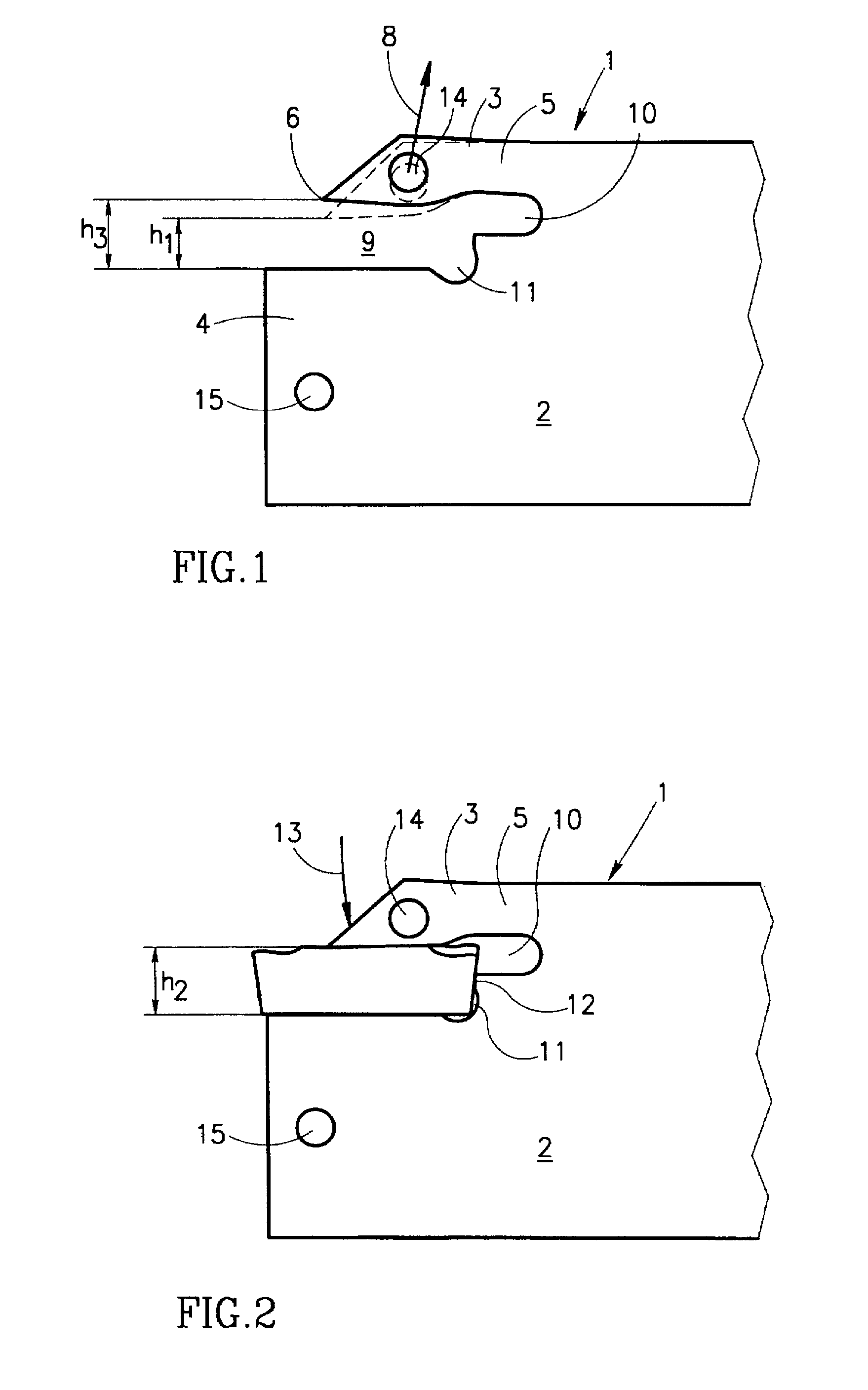
[0019]As seen in FIG. 1 of the drawings, a holder blade 1 for a metal cutting tool assembly in accordance with the present invention comprises a rigid body portion 2 with which are formed integrally a clamping jaw 3 and a base jaw 4. The clamping jaw 3 is coupled to the body portion 2 via a relatively narrow neck portion 5, thereby allowing for a limited degree of flexible resilience of the clamping jaw 3 with respect to the body portion 2 and with respect to the base jaw 4, the latter forming a rigid whole with the body portion 2.

[0020]As can be seen in dotted lines in FIG. 1 of the drawings, the clamping jaw 3, in its unstressed position, has its forward tip 6 directed downwardly towards the base jaw 4 and is spaced therefrom by a distance h1.

[0021]In order to allow for the introduction of an insert 7 (shown in FIG. 2 of the drawings) having a height h2, the clamping jaw 3 must be displaced upwardly in the direction of the arrow 8 (FIG. 1) so that its forward tip 6 is spaced from ...


PUM

PropertyMeasurementUnit
rigidaaaaaaaaaa
displacementaaaaaaaaaa
displacing forceaaaaaaaaaa

Abstract

A metal cutting tool assembly comprising a rigid holder blade, an insert receiving slot formed in a leading end of the holder blade and defined between a resiliently displaceable clamping jaw formed integrally with the holder blade and rigid base jaw forming part of the holder blade, spaced apart displacement and supporting surfaces respectively formed in or on the clamping jaw and the holder, and a slot opening key, with a pair of spaced apart projecting prongs of the key adapted to engage the surfaces. At least one of the prongs is displaceable with respect to the holder blade so as resiliently to displace the clamping jaw outwardly with respect to the base jaw into an opening position for insertion or removal of an insert.

Description

FIELD OF THE INVENTION[0001]This invention relates to metal cutting tool assemblies of the kind wherein an exchangeable cutting insert is releasably retained in an insert retaining slot formed in a holder blade. The invention relates particularly to such a cutting tool assembly wherein the insert is retainably clamped within the retaining slot between a resiliently displaceable clamping jaw and a rigid base jaw without the use of additional mechanical clamping means such as clamping screws or the like.BACKGROUND OF THE INVENTION[0002]One known form of cutting tool assembly of the kind to which the invention relates involves the so-called “wedge clamping” of the insert in the insert retaining slot. Here, the insert, having a single cutting edge, is provided with a wedge-shaped body which forcibly inserted and is retained within a correspondingly wedge-shaped retaining slot, the actual clamping of the insert within the slot being effected by the resilient outward displacement of the c...

Claims


Application Information

Patent Timeline
Patent Type & Authority Patents(United States)
IPC IPC(8): B23B27/04B23B27/16B23D61/04F16B2/20
CPCB23B27/04B23B2205/02B23B2260/0785Y10T82/2589Y10T407/25Y10T407/194Y10T407/2286Y10T29/49822Y10T29/49945Y10T407/2288B23B29/24
Inventor FRIEDMAN, JACOB
Owner ISCAR LTD
Learn More