

Non-microphone voice transmission device
A voice transmission and microphone technology, applied in sensors, sensor parts, transducer circuits, etc., can solve problems such as low signal-to-noise ratio, and achieve the effects of low distortion, good confidentiality, and good radiation resistance.
- Summary
- Abstract
- Description
- Claims
- Application Information
AI Technical Summary
Problems solved by technology
Method used
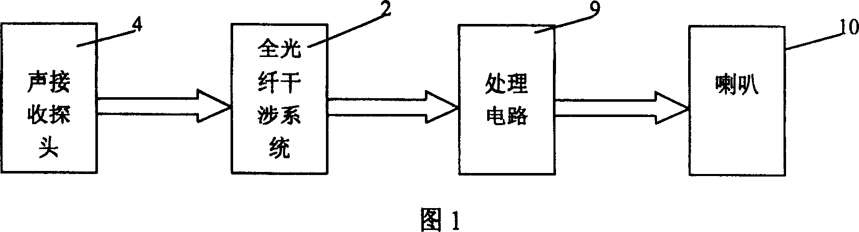
Image

Examples
example 1
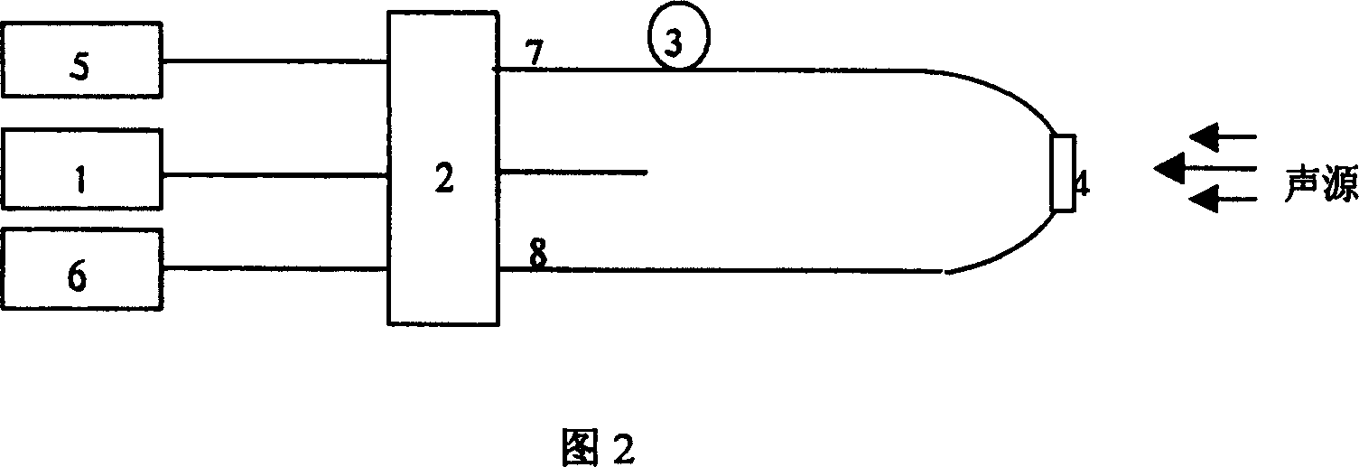
[0033] Example 1: Consists of a 3×3 fiber coupler, and its structure is shown in Figure 2.
[0034] The light emitted by the stable light source 1 is connected through the jumper FC / PC and enters the 3×3 fiber coupler 2. After being split, the light from port 7 of the coupler passes through the fiber delay line 3, and then passes through the sound receiving device 4 The hour hand is transmitted to port 8. The light of the port 8 first passes through the sound receiving device 4 and then is transmitted to the port 7 through the optical fiber delay line 3 counterclockwise. The two light beams form an optical signal carrying the physical characteristics of the acoustic receiving device in the 3×3 fiber coupler 2, which is received by the detectors 5 and 6. By inverting the interference signal, the physical characteristics of the acoustic receiving device 4 are finally obtained.
example 2
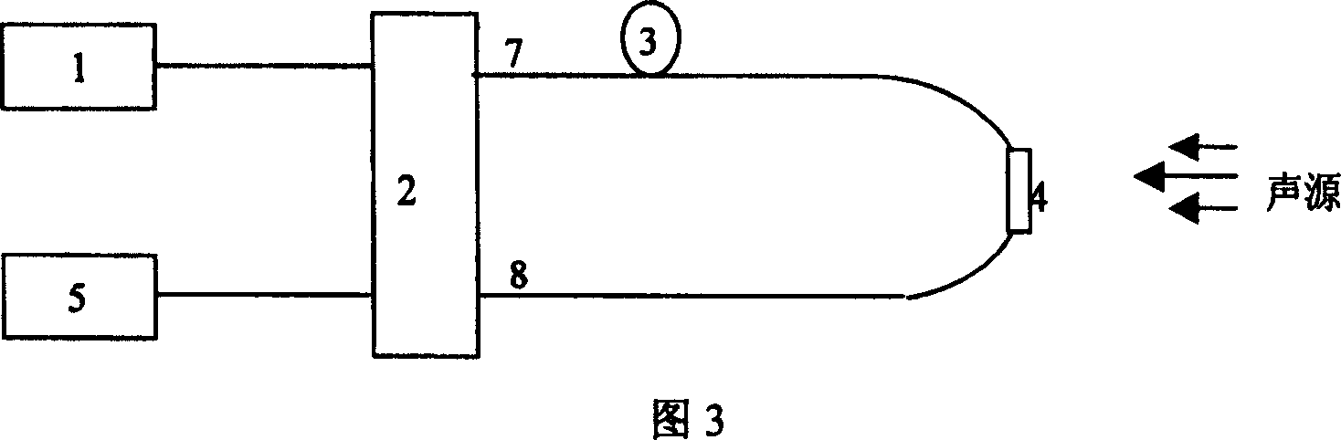
[0035] Example 2: Consists of 2×2 fiber couplers, and its structure is shown in Figure 3.
[0036] The light emitted by the stable light source 1 passes through the 2×2 fiber coupler 2, and after being split, the light from port 7 passes through the fiber delay line 3 and then passes through the sound receiving device 4 and transmits clockwise to port 8, and the light from port 8 first passes through the sound receiving device After 4, it is transmitted counterclockwise to port 7 through the optical fiber delay line 3. The two light beams form an optical signal carrying the physical characteristics of the acoustic receiving device in the 2×2 fiber coupler 2 and are received by the detector 5. By inverting the interference signal, the physical characteristics of the acoustic receiving device 4 are finally obtained.
[0037] The working principles of the two structures of Example 1 and Example 2 are the same, except that in the structure shown in Example 1 (Figure 2), there are two ...
PUM
 Abstract
Description
Claims
Application Information