Microwave optical signal wireless laser transmission device and method

A wireless laser and transmission device technology, applied in the direction of free space transmission, etc., can solve the problems of optical fiber unable to microwave optical signal long-distance wireless laser transmission, application limitations of microwave photonics technology, etc., to achieve anti-electromagnetic interference and good confidentiality, antenna The effect of small size and small terminal size

Pending Publication Date: 2020-07-28
哈尔滨天陆智成光电科技有限责任公司
View PDF0 Cites 1 Cited by
  • Summary
  • Abstract
  • Description
  • Claims
  • Application Information

AI Technical Summary

Problems solved by technology

In existing microwave photonics systems, optical fibers are usually used for point-to-point signal transmission, but for two platforms with relative motion, long-distance wireless laser transmission of microwave optical signals cannot be carried out by using optical fibers, which makes the application of microwave photonics technology restricted. limit
The main difficulty in long-distance wireless laser transmission of microwave optical signals is to achieve precise beam alignment between two high-speed operating platforms and to control the spatial optical transmission loss within a certain range.

Method used


Image

  • Microwave optical signal wireless laser transmission device and method
  • Microwave optical signal wireless laser transmission device and method

Examples


Embodiment Construction

[0023] The technical solutions in the embodiments of the present invention will be clearly and completely described below in conjunction with the drawings in the embodiments of the present invention.

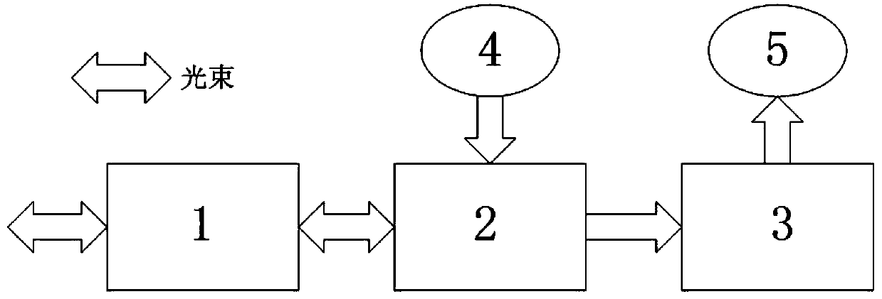
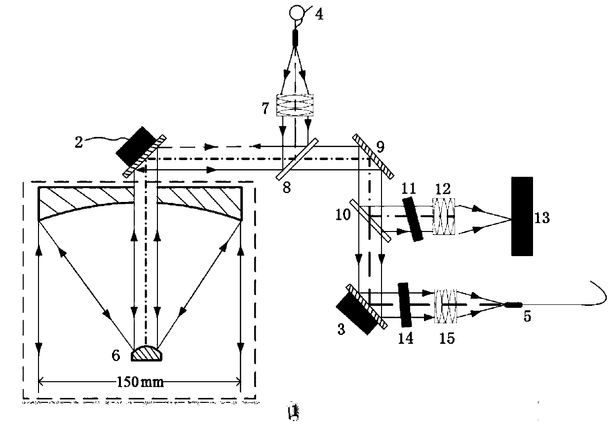
[0024] see Figure 1-2 Describe this embodiment, a microwave optical signal wireless laser transmission device, which includes a first tracking unit 1, a second tracking unit 2, an alignment unit 3, a signal transmitting optical fiber 4 and a signal receiving optical fiber 5, the first tracking unit 1 is interconnected with the second tracking unit 2, the second tracking unit 2 is connected to the alignment unit 3, the signal transmitting optical fiber 4 is connected to the second tracking unit 2, and the alignment unit 3 is connected to the signal receiving optical fiber 5, An optical antenna 6 is arranged in the first tracking unit 1 .

[0025] In this embodiment, the first tracking unit 1 , the second tracking unit 2 and the alignment unit 3 form a three-stage compound beam ...


PUM

PropertyMeasurementUnit
emissivityaaaaaaaaaa

Abstract

The invention provides a microwave optical signal wireless laser transmission device and method, and belongs to the technical field of microwave optical signal transmission. The problem that in the prior art, microwave optical signal long-distance wireless laser transmission cannot be conducted between two platforms moving relatively is solved. The device comprises a first tracking unit, a secondtracking unit, an alignment unit, a signal transmitting optical fiber and a signal receiving optical fiber, wherein the first tracking unit is connected with the second tracking unit, the second tracking unit is connected with the alignment unit, the signal transmitting optical fiber is connected with the second tracking unit, the alignment unit is connected with the signal receiving optical fiber, and an optical antenna is arranged in the first tracking unit. The device and method are mainly used for long-distance wireless laser transmission of microwave optical signals.

Description

technical field [0001] The invention belongs to the technical field of microwave optical signal transmission, and in particular relates to a microwave optical signal wireless laser transmission device and a transmission method. Background technique [0002] Microwave photonics is a new interdisciplinary subject that combines the advantages of microwave and optics with the continuous development of semiconductor lasers, light-speed photoelectric modulator detectors, integrated optics, fiber optics and microwave technology. Microwave optical signal in microwave photonics is to apply optical technology to microwave system, and use the unique advantages of optical system such as low loss and large bandwidth to transmit and process microwave signal. In existing microwave photonics systems, optical fibers are usually used for point-to-point signal transmission, but for two platforms with relative motion, long-distance wireless laser transmission of microwave optical signals cannot...

Claims


Application Information

Patent Timeline
Patent Type & Authority Applications(China)
IPC IPC(8): H04B10/11
CPCH04B10/11
Inventor 于思源丛聪郭鹏
Owner 哈尔滨天陆智成光电科技有限责任公司
Why Eureka
Try Eureka