
Fluidized bed exhaust gas desulfurizing method and desulfurizing installation

A fluidized bed and flue gas technology, applied in separation methods, chemical instruments and methods, and separation of dispersed particles, can solve problems such as large system resistance, increased dust collector load, and large water consumption for desulfurization treatment, achieving low operating costs Effect

Inactive Publication Date: 2007-11-21
刘继昆
View PDF4 Cites 0 Cited by
  • Summary
  • Abstract
  • Description
  • Claims
  • Application Information

AI Technical Summary

Problems solved by technology

The shortcomings of CFB-FGD are: due to the high concentration of solid materials, the load of the dust collector is increased, and the system resistance is relatively large; the operating cost is similar to that of the ordinary spray drying method; the utilization of desulfurization by-products still needs further development and research
[0005] In particular, it should be pointed out that because CaO in the lime method is insoluble in water (0.165g / 100g water), the water consumption of desulfurization treatment is huge, resulting in a large amount of waste of water resources, which is not suitable for the serious water shortage in my country.

Method used


Image

  • Fluidized bed exhaust gas desulfurizing method and desulfurizing installation

Examples


Embodiment 1

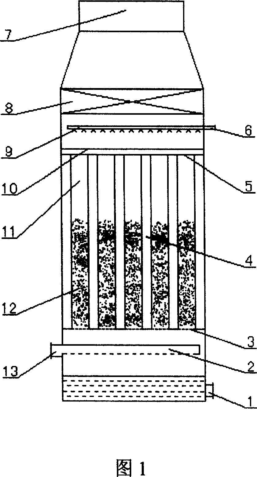
[0018] The structure of the fluidized bed desulfurization device is shown in Figure 1, including a fluidized bed desulfurization tower 4, an absorption liquid inlet 6 on the tower body, an absorption liquid outlet 1, a flue gas inlet 13, and a flue gas discharge channel 7, which are supported in the tower body A number of tubular absorbers 11 are vertically installed between the board 3 and the flower board 5, and filled with lightweight spherical packing 12 with a diameter of 18mm and made of PVC, and the filling height is 950mm; the spray device 9 is installed on the flower board 5 is connected to the absorption liquid inlet 6 on the tower body; the flow divider 2 connected to the flue gas inlet 13 is installed under the support plate 3; the absorption liquid outlet 1 is installed at the bottom of the tower body, and the flue gas discharge channel 7 is installed At the top of the tower body, a block 10 is installed on the flower plate 5 to prevent the light spherical filler 1...

Embodiment 2

[0022] The structure of the ebullating bed desulfurization device is the same as in Example 1, and the tubular absorber 11 is filled with lightweight spherical fillers 12 with a diameter of 20 mm and made of ABS, and the filling height is 200 mm; 2 The flue gas enters the tower from the lower flue gas inlet 13 of the fluidized bed desulfurization tower 4, and after being divided by the flow splitter 2, enters the tubular absorber 11 at a flow rate of 20m / s, and sprays the light spherical packing 12 into a boiling state ; The carbonamide absorbent with a concentration of 25% enters the tower from the absorption liquid inlet 6, and passes through the spray device 9 at a distance of 37m 3 / m 2 The spray density of h is sprayed down from the upper part of the fluidized bed desulfurization tower in the form of droplets, and contacts with the flue gas and packing to form a gas-liquid-solid three-phase high-speed collision, which strengthens the mass transfer coefficient and the SO i...


PUM


Abstract

The present invention relates to a boiling-bed flue gas desulfurizing method and desulfurizing equipment. It is characterized by that in the tubular absorber of the desulfurizing tower the light ball filler is filled, the flue gas containing SO2 can be divided at high speed and fed into the tubular absorber from the lower portion of the desulfurizing tower of boiling bed, the light ball filler can be sprayed by said flue gas and formed into boiling state, and can be contacted with mist droplet-shaped carbamide absorbent downwards sprayed from upper portion of desulfurizing tower so as to form gas-liquid-solid three phase mutural collision, so that the SO2 in the flue gas can be reacted with carbamide to form ammonium sulfate and the flue gas can be purified.

Description

technical field [0001] The invention relates to a flue gas desulfurization method, in particular to a flue gas desulfurization method using a fluidized bed, and also relates to a desulfurization device suitable for the flue gas desulfurization method. Background technique [0002] At present, the flue gas desulfurization (FGD) technology applied in industry can be divided into dry method (including semi-dry method) and wet method. Dry desulfurization is the use of solid absorbents, adsorbents or catalysts to remove SO from exhaust gas 2 , The commonly used methods are activated carbon adsorption, molecular sieve adsorption, oxidation and metal oxide absorption. The advantage is that there is no discharge of waste water and waste acid during treatment, which reduces secondary pollution; the disadvantage is that the desulfurization efficiency is low and the equipment is huge. Wet desulfurization is the use of liquid absorbent to scrub flue gas to remove SO 2 , The commonly ...

Claims


Application Information

Patent Timeline
Patent Type & Authority Patents(China)
IPC IPC(8): B01D53/50B01D53/83
Inventor 刘继崑刘琦
Owner 刘继昆
Learn More