Method and circuit for improving display quality for liquid crystal display screen
A liquid crystal display and circuit technology, applied to static indicators, instruments, etc., can solve the problems of high tolerance of burst pulse signal, unstable frequency of burst pulse signal, etc., and achieve the effect of reducing interference noise
- Summary
- Abstract
- Description
- Claims
- Application Information
AI Technical Summary
Problems solved by technology
Method used
Image
Examples
no. 1 example
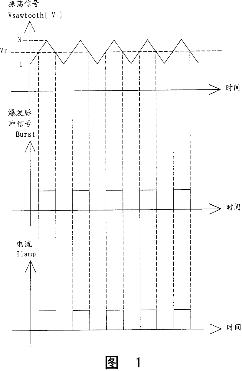
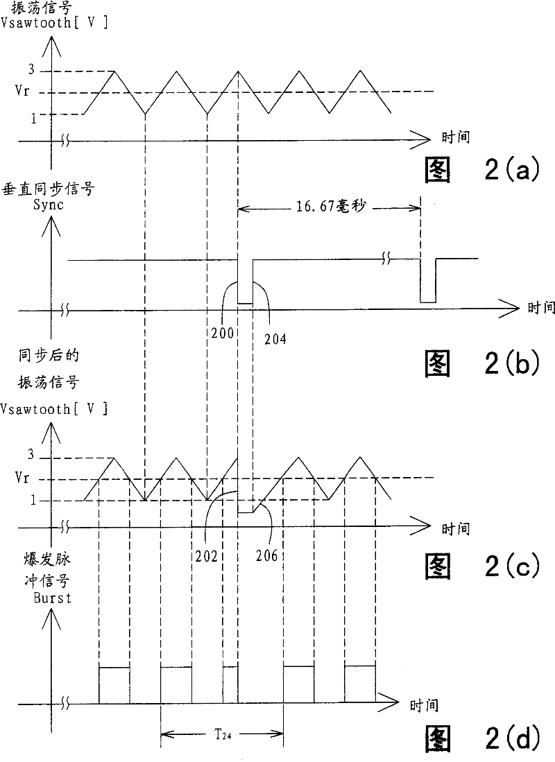
[0019] An embodiment of the method of the present invention is described below. In this embodiment, a liquid crystal display system includes a Video Graphics Array (VGA) type liquid crystal display panel, lamps for generating light, and an explosive direct AC converter. The liquid crystal display panel includes an array of liquid crystal display pixels, and the light generated by the lamp is irradiated to the liquid crystal display panel. The burst DC-AC converter drives the lamps, and is often referred to as a backlight DC-AC converter if the lamps are placed behind the LCD pixel array. For a video image array type liquid crystal display panel, there are 480 pixel rows in the pixel array, that is, 480 pixel units in each pixel column. A video signal is supplied to the liquid crystal display system. Furthermore, the oscillating signal Vsawtooth generated by the burst DC-AC converter is a sawtooth waveform signal, and the oscillating signal Vsawtooth (unit is volt V) is shown...
no. 2 example
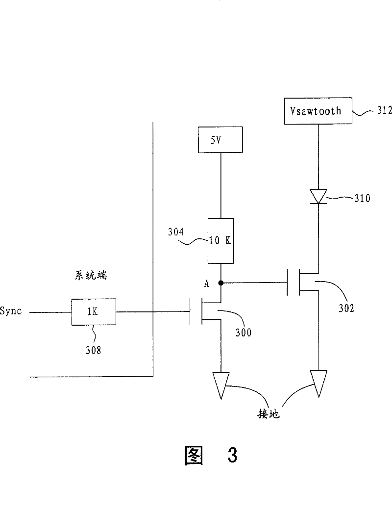
[0026] Herein, in order to implement the above method, the present invention further provides an embodiment of a related circuit. Please refer to the circuit in FIG. 3. In this circuit, two semiconductor switches, such as two N-type metal oxide semiconductor field effect transistors (NMOSFETs) 300 and 302, are used as switches. The first transistor 300 and a resistor 304 are connected to node A and connected to ground as a reference potential. Resistor 304 has a value of 10 kilo-ohms (K), and resistor 304 is connected to a DC voltage of 5 volts (V), which may be from a power source and when applied to the second transistor 302. When controlling the terminal, the DC voltage must be able to turn on the second transistor 302 . The control terminal of the first transistor 300 receives the vertical synchronization signal Sync with the waveform shown in FIG. 2( b ) via the resistor 308 , and the value of the resistor 308 is 1,000 ohms. The second transistor 302 is connected to a d...
no. 3 example
[0030] Another embodiment of the circuit provided by the present invention for implementing the above method is described herein. Like the possibility mentioned above, when the waveform of the vertical synchronization signal Sync is the opposite of the signal waveform in Fig. 2(b) (the original oscillating signal Vsawtooth remains unchanged, and the waveform is shown in Fig. 2(a)), then Fig. The circuit in 3 can be modified to use a P-type metal-oxide-semiconductor transistor (PMOSFET) instead of the first transistor 300 (which is an N-type metal-oxide-semiconductor transistor), as shown in FIG. 4 . In FIG. 4 , the first transistor 400 is a P-type MOS transistor, and the second transistor 402 is still an N-type MOS transistor, and other components and connection methods are the same as the circuit in FIG. 3 .
[0031] The principle of operation of this circuit is described below. When the vertical synchronization signal Sync transitions to a high value, the first transistor 4...
PUM
 Abstract
Description
Claims
Application Information
 - R&D
- Intellectual Property
- Life Sciences
- Materials
- Tech Scout
- Unparalleled Data Quality
- Higher Quality Content
- 60% Fewer Hallucinations
Browse by: Latest US Patents, China's latest patents, Technical Efficacy Thesaurus, Application Domain, Technology Topic, Popular Technical Reports.
© 2025 PatSnap. All rights reserved.Legal|Privacy policy|Modern Slavery Act Transparency Statement|Sitemap|About US| Contact US: help@patsnap.com


