Supercharge Your Innovation With Domain-Expert AI Agents!

Shaft hole part and shaft connection structure

A technology that combines structure and shaft hole, applied in the direction of bearing components, shafts and bearings, rigid shaft couplings, etc., can solve problems such as impossible, unobtainable, and cost-intensive

Inactive Publication Date: 2007-12-19
SUMITOMO HEAVY IND LTD
View PDF8 Cites 3 Cited by
  • Summary
  • Abstract
  • Description
  • Claims
  • Application Information

AI Technical Summary

Problems solved by technology

[0014] However, the combination structure of the shaft hole and the shaft with no gap between the shaft hole and the shaft by press-fitting, hot-press fitting, etc. in the above (1) does have the corresponding effect of preventing fretting wear, but it takes a lot of work to assemble and disassemble. , and whether it is heated or pressed in with a large load, there are many cases where it is impossible to realize the structure
[0015] The joint structure caused by the frictional connection using the wedge effect in the aforementioned (2) requires the orientation of the shaft hole part and the shaft to be correct, which inevitably leads to high costs. In addition, a large space is necessary
[0016] The combination structure of the above (3) coating lubricant on the contact surface can indeed obtain the expected effect of preventing fretting wear at the initial stage of operation, but the desired effect cannot be obtained in long-term operation. As an implementation countermeasure, it has to be said that an imperfect structure
In addition, there must be a special structure to prevent the leakage of lubricating oil
[0017] Although the combination structure of coating or spraying a special protective film on the contact surface of the above (4) is proposed by many, however, like the above (3), the protective film will be peeled off anyway by operation, There is a problem that the effect cannot be obtained continuously for a long time
In addition, due to special processing, the cost must be high
[0018] In this way, although many proposals have been proposed as a joint structure for preventing fretting wear in the past, in fact, there is a problem that these are not practical.

Method used


Image

  • Shaft hole part and shaft connection structure
  • Shaft hole part and shaft connection structure
  • Shaft hole part and shaft connection structure

Examples


Embodiment Construction

[0028] Hereinafter, embodiments of the present invention will be described in detail with reference to the drawings.

[0029] In this embodiment, the present invention is applied to a coupling portion that connects the motor shaft of the motor not shown in the drawings with the input shaft of the speed reducer.

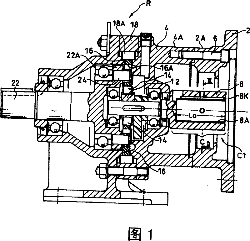
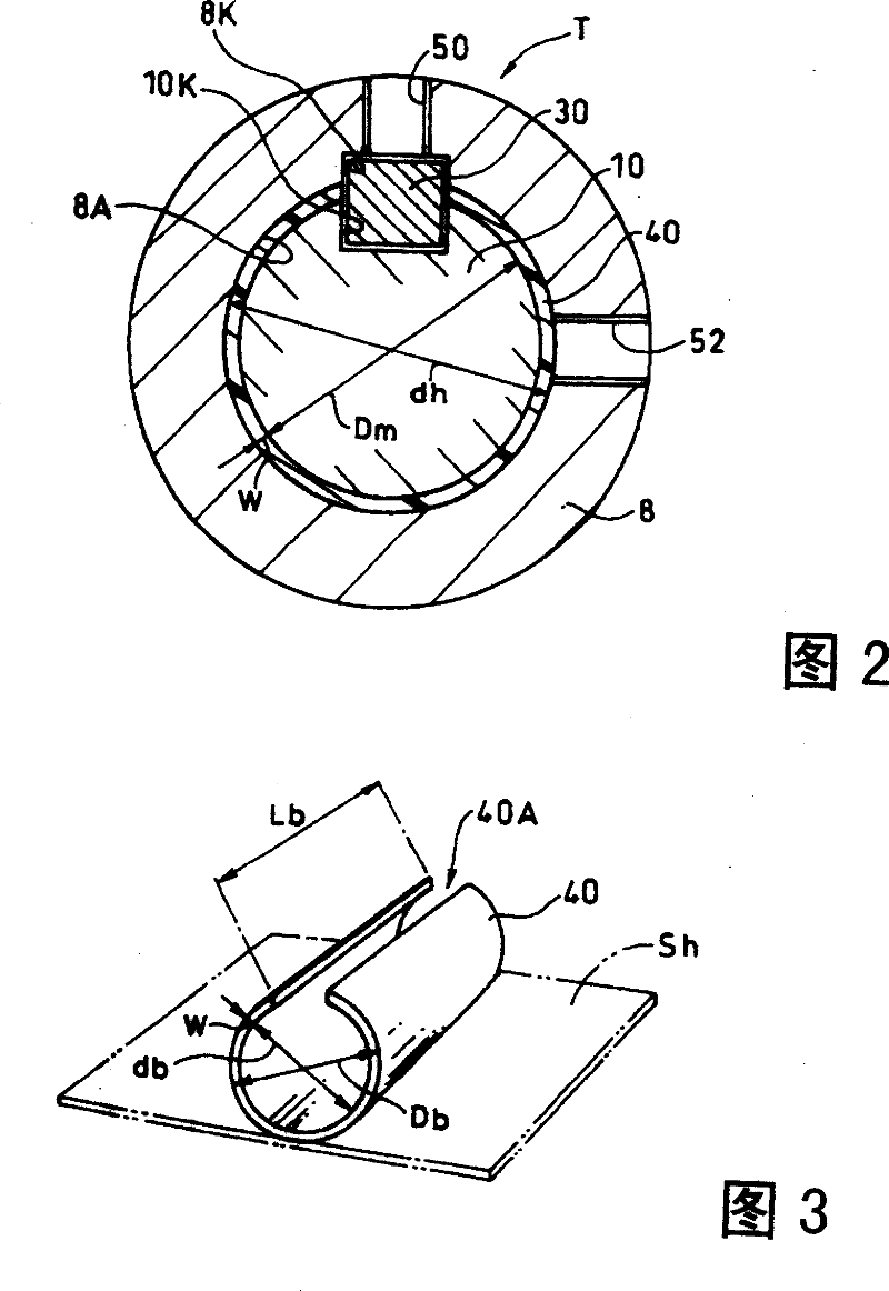
[0030] In FIG. 1 and FIG. 2 , symbol 2 is a connecting sleeve connected to a motor not shown in the figure, and 4 is a sleeve on the input side of the reducer R. The connecting sleeve 2 is connected to the sleeve 4 on the input side by bolts 6 , and the input shaft (shaft hole member) 8 of the speed reducer extends to the inside of the ring portions 2A, 4A of the sleeves 2 , 4 . A coupling portion C (described in detail later) between the input shaft 8 and the motor shaft 10 (refer to FIG. 2 , which is omitted in FIG. 1 ) is formed on the extension portion, that is, the base end portion of the input shaft 8 of the reducer R.

[0031] The speed reducer R itself is kno...


PUM


Abstract

The subject of this invention is to provide a structure capable of preventing the fretting of a shaft hole and a shaft for long period with a simple and low cost structure. An iron / steel input shaft 8 (shaft hole member) having a shaft hole 8A and an iron / steel motor shaft 10 fitted into the shaft hole 8A of the input shaft 8 are connected to each other through a power transmission part formed of a keyways 8K and 10K and a key 30. A resin (non-ferrous) bush 40 is provided in the areas between the inner peripheral surface of the shaft hole 8A and the outer peripheral surface of the motor shaft 10 excluding the areas of the keyways 8K and 10K.

Description

technical field [0001] The present invention relates to an iron-based shaft hole member having a shaft hole, such as a hollow shaft of a reducer or a coupling, and an iron-based shaft that fits into the inner periphery of the shaft hole with a small gap. , through the power transmission part formed on a part of the circumferential direction, it is combined into a structure that can transmit power. Background technique [0002] When a part with a shaft hole (shaft hole part) such as a hollow shaft of a reducer or a coupling is combined with a shaft so that power can be transmitted, it is widely used to insert a shaft whose outer diameter is only slightly smaller than the inner diameter of the shaft hole. In the shaft hole, the method of combining key grooves and keys respectively formed on the inner circumference of the shaft hole and the outer circumference of the shaft. [0003] In addition, there is also generally known a structure in which a protruding portion is provide...

Claims


Application Information

Patent Timeline
Patent Type & Authority Patents(China)
IPC IPC(8): F16H57/00F16D1/08F16C33/12F16C33/14F16D1/06
CPCF16D1/0876A46B15/0069A46B2200/1066
Inventor 山本章
Owner SUMITOMO HEAVY IND LTD
Features
  • R&D
  • Intellectual Property
  • Life Sciences
  • Materials
  • Tech Scout
  • Unparalleled Data Quality
  • Higher Quality Content
  • 60% Fewer Hallucinations
Learn More