Motor controller

一种电机控制、控制对象的技术,应用在电动机控制、交流电动机控制、电动控制器等方向,能够解决调整困难、麻烦等问题,达到调整简单的效果

Inactive Publication Date: 2007-12-26
MITSUBISHI ELECTRIC CORP
View PDF4 Cites 2 Cited by
  • Summary
  • Abstract
  • Description
  • Claims
  • Application Information

AI Technical Summary

Problems solved by technology

In addition, since it is cumbersome to set these parameters individually, and knowledge for setting them appropriately is required, adjustment is difficult for inexperienced people.

Method used


Image

  • Motor controller
  • Motor controller
  • Motor controller

Examples


Embodiment Construction

[0018] Embodiment 1

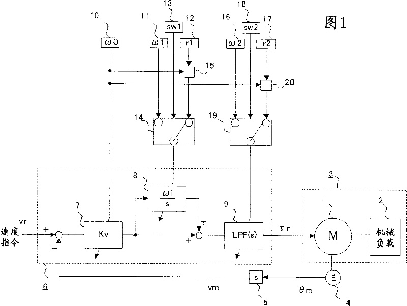
[0019] Fig. 1 is a block diagram of a motor control device according to Embodiment 1 of the present invention. The motor 1 drives the control object 3 composed of the motor 1 and the mechanical load 2 matching it by generating a torque corresponding to the torque command τr. In addition, the encoder 4 detects the motor angle θm which is the rotation angle of the motor 1 , and by differentiating the motor angle θm by the speed calculator 5 , the motor speed vm which is the rotation speed of the motor 1 is detected.

[0020] Next, the feedback calculation unit 6 inputs the speed command vr and the motor speed vm, and calculates the torque command τr through the operation described below.

[0021]Inside the feedback operation unit 6, the difference signal between the speed command vr and the motor speed vm is input to the speed proportional amplifier 7, and the speed proportional amplifier 7 outputs a signal multiplied by the speed gain Kv on its input. Th...


PUM


Abstract

To provide a motor control device, capable of simply making an adjustment accordance to the control specifications, and making an optimum adjustment appropriate to applications, in a short time.A motor control device includes a feedback computing portion for inputting position command signals or speed command signals and motor revolution signals, and for computing torque commands by computations in which a transfer function of a feedback loop from the motor revolution signals to torque command signals includes a peak or a zero point, a response parameter input portion, and a ratio parameter input portion. A loop gain, i.e. the gain of the feedback loop is set, according to the response parameter, and the peak or the zero point of the feedback loop is set, such that the ratio between the response frequency that is a value obtained by dividing a loop gain by the inertial value targeted for control, and a frequency corresponding to a peak or zero point of the feedback loop, according to the response parameter and the ratio parameter, reaches a value set by the ratio parameter, thereby facilitating adjustment in a short time.

Description

technical field [0001] The present invention relates to a motor control device used as a drive device for a machine tool, a semiconductor manufacturing device, various conveying devices, and the like. Background technique [0002] In the motor control device, it is necessary to generate a command through the calculation of the feedback loop of the torque command based on the motor speed or the motor angle, and it is necessary to appropriately set the loop gain, the zero frequency in the speed PI control, the filter frequency, the feedback The poles and zeros of the transfer function of the ring, etc. In addition, since it is cumbersome to set these parameters individually, and knowledge for setting them appropriately is required, adjustment is difficult for inexperienced persons. [0003] As a conventional technology to improve this point, for example, one input parameter is input from the outside, and a specific relational expression is used from the input parameter, and b...

Claims


Application Information

Patent Timeline
Patent Type & Authority Patents(China)
IPC IPC(8): H02P23/00G05B11/36G05B13/02G05D3/12
CPCH02P27/026H02P2205/05Y10S388/906
Inventor 池田英俊
Owner MITSUBISHI ELECTRIC CORP
Why Eureka
Try Eureka