Fuel battery with constant pressure air as oxidant and coolant

A fuel cell and oxidant technology, which is applied to fuel cells, battery electrodes, circuits, etc., can solve the problems of poor low-temperature startup performance of battery stacks and poor low-temperature operability of battery stacks, and achieve improved low-temperature startup performance and energy consumption. The effect of low, lower volumetric specific heat capacity

Inactive Publication Date: 2008-01-09
SHANGHAI MUNICIPAL ELECTRIC POWER CO +2
View PDF2 Cites 0 Cited by
  • Summary
  • Abstract
  • Description
  • Claims
  • Application Information

AI Technical Summary

Problems solved by technology

At the same time, the use of water as the coolant fuel cell makes the low-temperature operability of the battery stack worse on the one hand, and on the other hand makes the low-temperature start-up performance of the battery stack worse

Method used


Image

  • Fuel battery with constant pressure air as oxidant and coolant
  • Fuel battery with constant pressure air as oxidant and coolant
  • Fuel battery with constant pressure air as oxidant and coolant

Examples


Embodiment 1

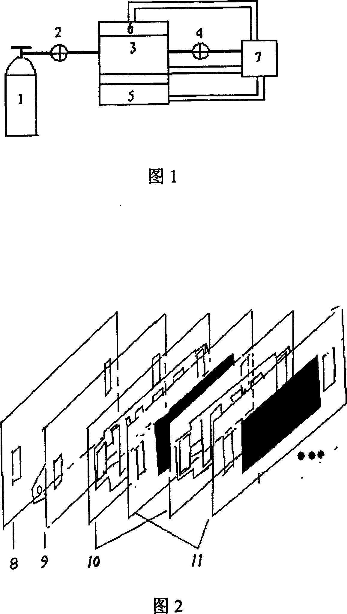
[0023] Accompanying drawing 1 has given the structural schematic diagram of whole battery system; Hydrogen storage tank 1 is a metal hydrogen storage tank, and a certain amount of hydrogen is stored in the tank, enters fuel cell stack 3 after passing through pressure reducing valve 2, and the outlet of fuel cell stack 3 is set There is a hydrogen flow control valve 4, 5 is a fan, which can directly use the electric energy generated by the fuel cell to provide air to the fuel cell, 6 is the air flow ratio adjustment device, and 7 is the battery system control circuit, which uses the power generated by the fuel cell Electric energy, provide electric energy for 4, 5, 6 and detect and control their running status.

[0024] The whole battery system works like this: the hydrogen in the hydrogen storage tank 1 enters the hydrogen gas side of the electrode plate of the fuel cell stack 3 after passing through the pressure reducing valve 2, and forms a superimposed voltage with the air o...

Embodiment 2

[0026] Attached Figure 2 shows a schematic diagram of battery stack assembly; 8 is the front and rear end plates of the battery stack, 9 is the current motherboard, 10 is the battery bipolar plate, and 11 is the three-in-one membrane electrode.

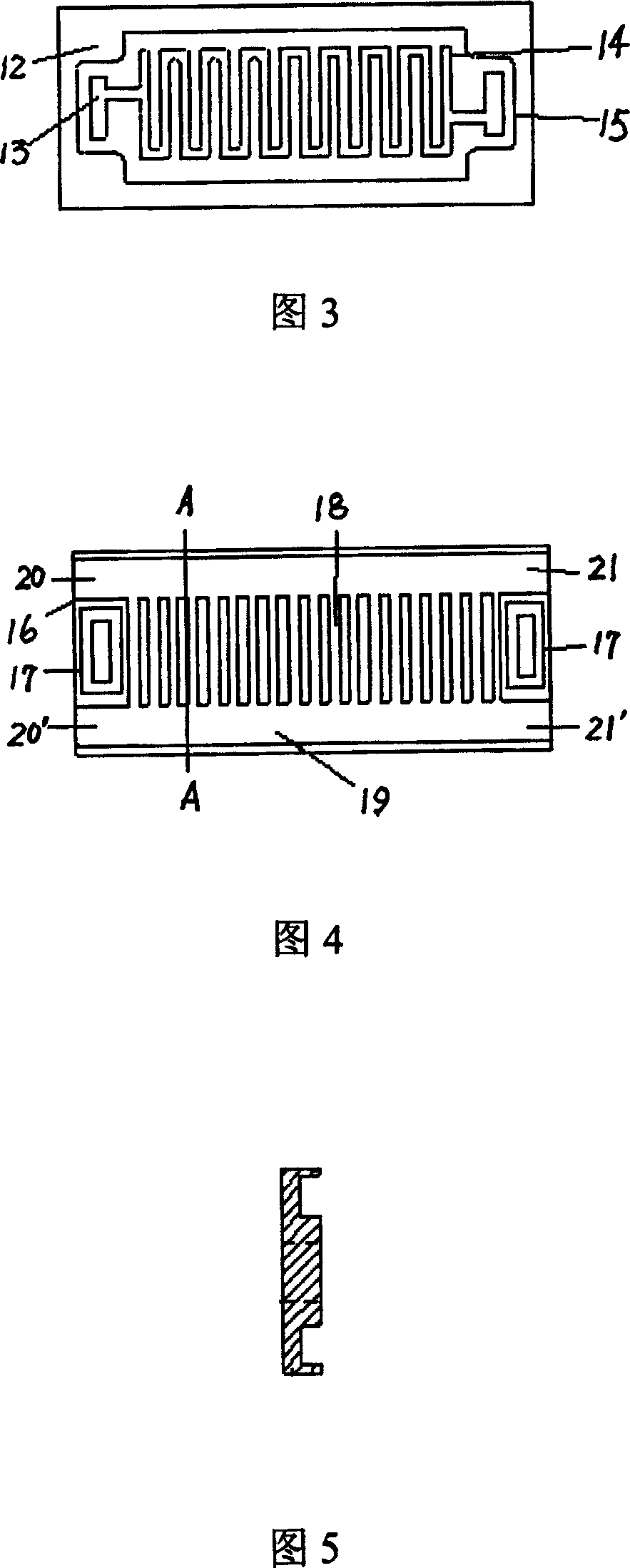
[0027] Accompanying drawing 3 has given the structure diagram of hydrogen gas side of bipolar plate 10; Among them, 12 bipolar plate hydrogen surface, 13 is hydrogen through-hole, 14 is hydrogen flow channel, 15 hydrogen sealing ring.

[0028] Accompanying drawing 4 has provided the air side structural diagram of bipolar plate 10; Wherein 16 is the air surface of bipolar plate, and sealing ring 17 is placed inside, and 18 is the reaction flow channel, and 19 is the cooling flow channel, and the air self-radiating flow channel entrance uses the same The wind pressure flows in at 20, 20' and flows out at the outlets 21, 21' of the flow channel to take away the heat generated by the battery. Among them, an air flow ratio adjustment devic...

Embodiment 3

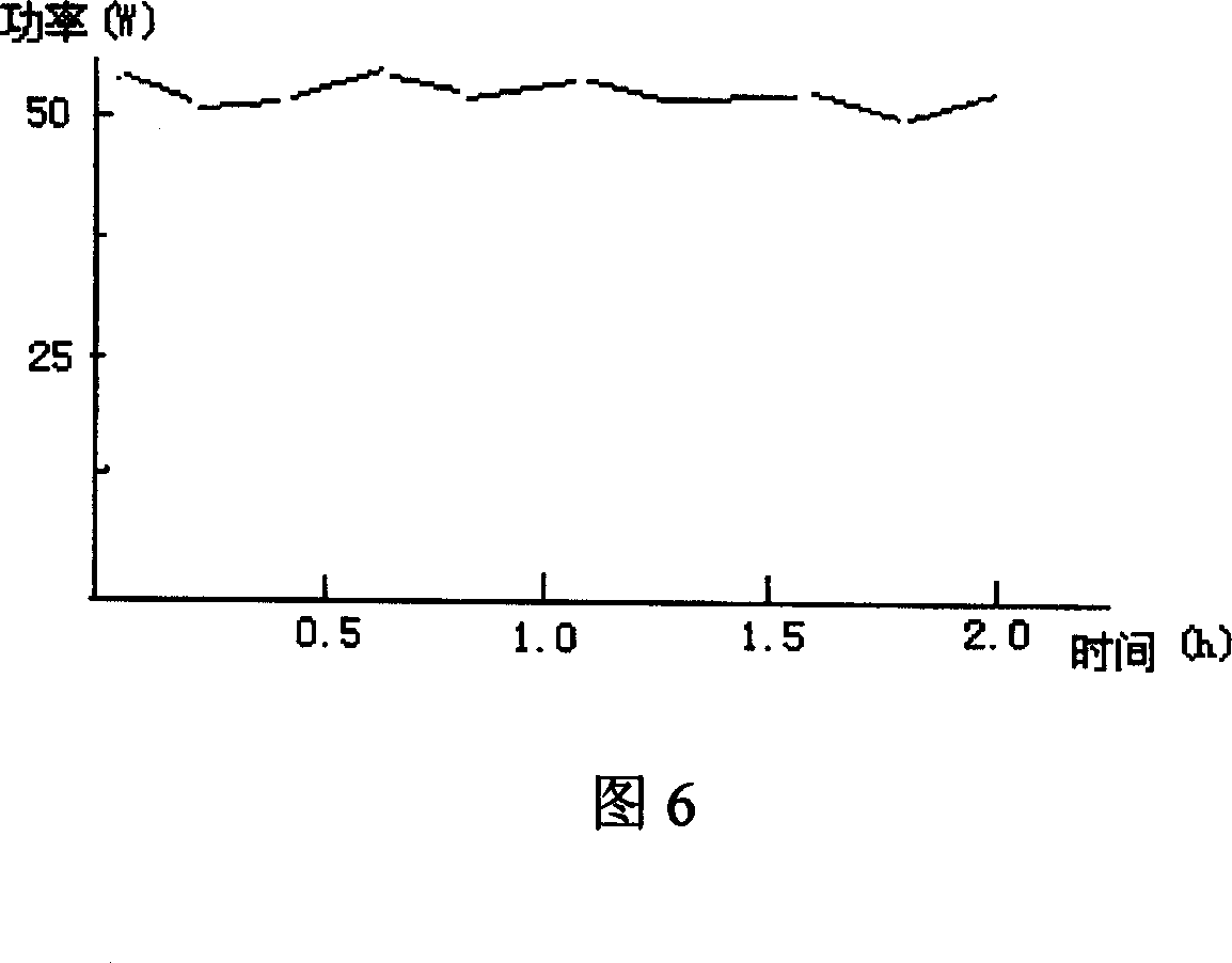
[0031] 50W integrated fuel cell system assembled with accompanying drawing 1. Among them, the bipolar plate adopts the method shown in attached drawing 3, attached drawing 4, and attached drawing 5. The area of ​​the bipolar plate is 45mm×100mm, and the effective area of ​​the three-in-one membrane is 25mm×80mm. 20 fuel cells are connected in series in the manner shown in Fig. 2 . The working temperature of the battery is 50°C, and when the output voltage of the battery is 12V, the current is about 4.5A, of which the power consumption of the fan is 2W (at this time, the ambient temperature is 30°C, and the power consumption of the fan varies with the ambient temperature), accounting for the entire battery stack 3.7% of output power. The power consumption of other control circuits and actuators is very low, about 0.2W. Accompanying drawing 6 has provided the battery output power (power supply voltage is 12V) with time variation relation curve; As can be seen from this figure,...


PUM

PropertyMeasurementUnit
thicknessaaaaaaaaaa

Abstract

The fuel cell includes battery pile, normal pressure air delivery equipment, device of hydrogen supply and control device. The said battery pile is composed of membrane electrodes, dual pole plate of guiding flow, and motherboard of current, and front and back end plates. The said dual pole plate of guiding flow includes hydrogen face and air face setup in back to back. There are hydrogen flow channel, in/out through hole for hydrogen and seal ring for the said channel and the through hole on the hydrogen face. There are reacting flow channel for air, heat dispersion flow channel for air and in/out through hole for hydrogen on the air face. The reacting flow channel for air is vertical in middle part of the air face. Heat dispersion flow channel for air is transverse at two ends of the reacting flow channel for air. Comparing with prior art, the invention possesses features of simple and compact structure, lower energy consumption and stable operation etc.

Description

technical field [0001] The invention relates to a fuel cell, in particular to a fuel cell using normal pressure air as an oxidant and a coolant. Background technique [0002] A fuel cell is a H 2 and O 2 A device that converts the chemical energy generated by the reaction into electrical energy. Because the battery has the characteristics of starting at room temperature, high conversion efficiency, high volume specific power density, and zero pollution of the product, it has become a research hotspot in the current international community. Fuel cells are widely used. Large fuel cells can be used as power sources for submarines and automobiles, and small fuel cells can be used as power sources for electric bicycles, notebook computers, digital cameras and other mobile electrical equipment. [0003] For a small fuel cell stack, it requires a simple, compact structure and less auxiliary equipment. Some small fuel cell stacks usually use gas supply equipment such as air pumps...

Claims


Application Information

Patent Timeline
Patent Type & Authority Patents(China)
IPC IPC(8): H01M8/00H01M4/86
CPCY02E60/50
Inventor 田丙伦董辉
Owner SHANGHAI MUNICIPAL ELECTRIC POWER CO
Why Eureka
Try Eureka