Test set of electronic component connection socket

A technology for connecting sockets and electronic components, applied in the field of test fixtures to confirm the welding status of connection points, can solve the problem of twice the time spent, and achieve the effect of reducing test procedures and shortening detection time

Inactive Publication Date: 2008-01-16
MITAC COMP (SHUN DE) LTD +1
View PDF4 Cites 0 Cited by
  • Summary
  • Abstract
  • Description
  • Claims
  • Application Information

AI Technical Summary

Problems solved by technology

Therefore, engineers need to spend twice the time to complete the confirmation work by measuring another normal motherboard and comparing them one by one.

Method used


Image

  • Test set of electronic component connection socket
  • Test set of electronic component connection socket
  • Test set of electronic component connection socket

Examples


Embodiment Construction

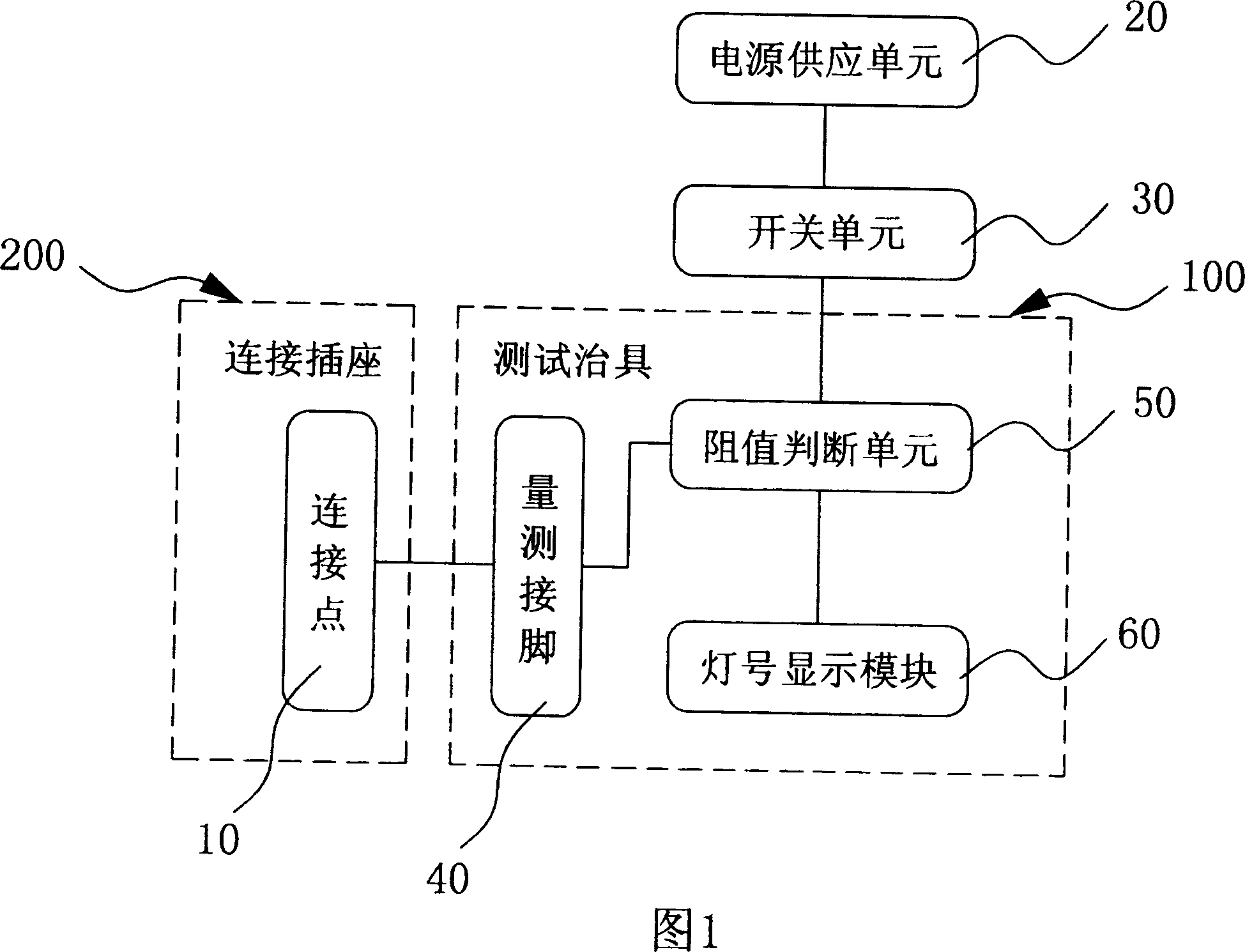
[0015] Please refer to FIG. 1 , the test mechanism includes a power supply unit 20 , a switch unit 30 , a connection socket 200 and a test fixture 100 . In this embodiment, the connection socket 200 can be a connection socket of a central processing unit. Switching through the switch unit 30 enables the power supply unit 20 to provide a test voltage to the test fixture 100, and uses its internal judgment circuit to confirm whether the grounding resistance of the connection socket 200 is normal, whether there is empty welding or cold welding at the connection point 10, etc. defective standards.

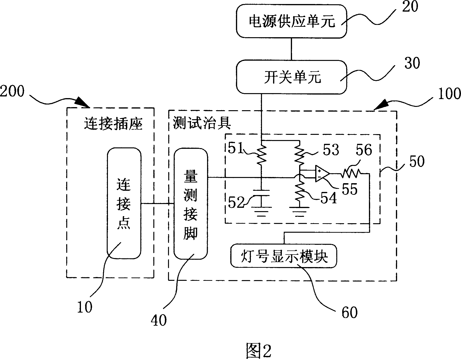
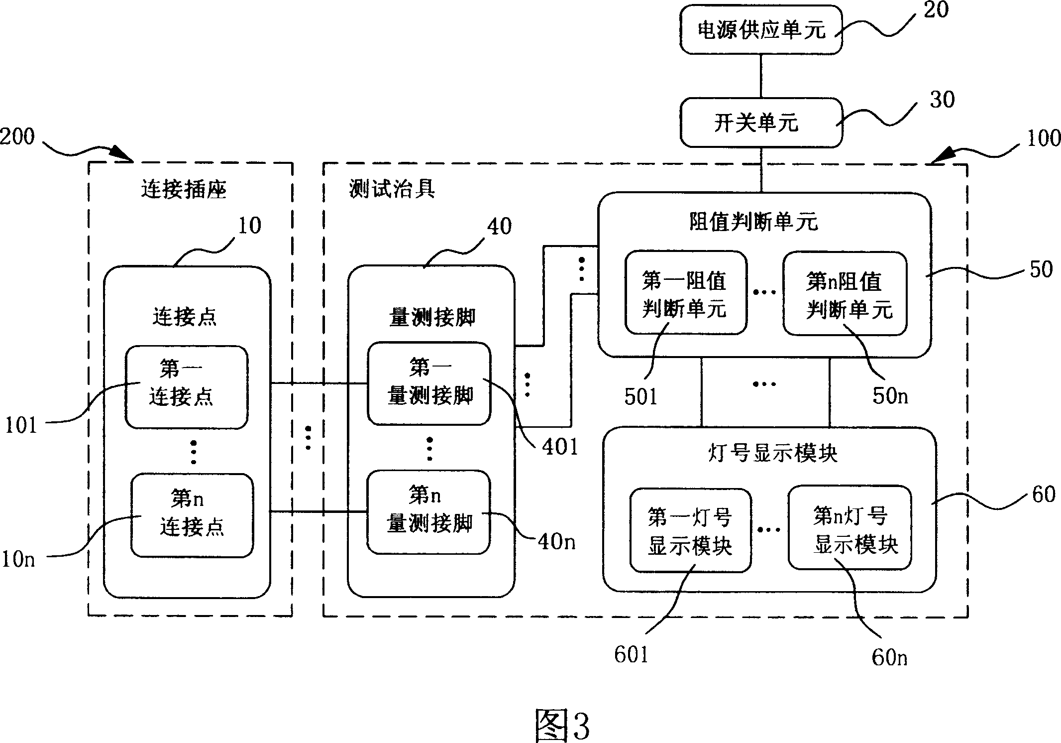
[0016] The test fixture 100 mainly includes: (A) measuring pin 40; (B) resistance judgment unit 50; and (C) light signal display module 60, respectively detailed as follows:

[0017] (A) The measurement pin 40 is used to electrically couple with the connection point 10. When the measurement pin 40 is electrically coupled with the connection point 10 through the connection socket 200, a...


PUM


Abstract

The invention is a test tool for connection socket of an electronic component, for determining welding conditions between the connection socket and mainboard, determining whether ground resistance of a connection point is between default values by resistance judgment unit and measuring pin and making lamp number display module switch corresponding display states, and thus making a user determine whether a connection point is cold welded or non-welded, etc, so as to raise detecting efficiency.

Description

【Technical field】 [0001] The invention relates to a test fixture, which is applied to the test of connecting sockets of electronic components, in particular to a test fixture for confirming the welding state of the connection point by confirming the grounding resistance of the connection point through a resistance value judging circuit. 【Background technique】 [0002] At present, when the computer executable platform is designed, most of the space is reserved for users to upgrade. Therefore, many upgradeable components are currently connected to the motherboard through dedicated connection sockets, so as to facilitate users' future upgrade operations. [0003] The production process of the motherboard mostly uses Surface Mounting Technology (SMT) to deal with the soldering problem between the components and the Printed Circuit Board (PCB), but it is necessary to use the SMT during the SMT operation. The solder paste, printing machine (SolderPaste Printer), component placemen...

Claims


Application Information

Patent Timeline
Patent Type & Authority Patents(China)
IPC IPC(8): G06F1/00G01R31/00
Inventor 詹益新罗国健
Owner MITAC COMP (SHUN DE) LTD
Why Eureka
Try Eureka