Network interface with filtering device
A filter device and network port technology, applied in the direction of data exchange details, etc., can solve the problems of low efficiency of filter capacitors and increased equipment costs, and achieve the effects of reducing area, saving costs, and avoiding parasitic inductance
- Summary
- Abstract
- Description
- Claims
- Application Information
AI Technical Summary
Problems solved by technology
Method used
Image

Examples
no. 1 example
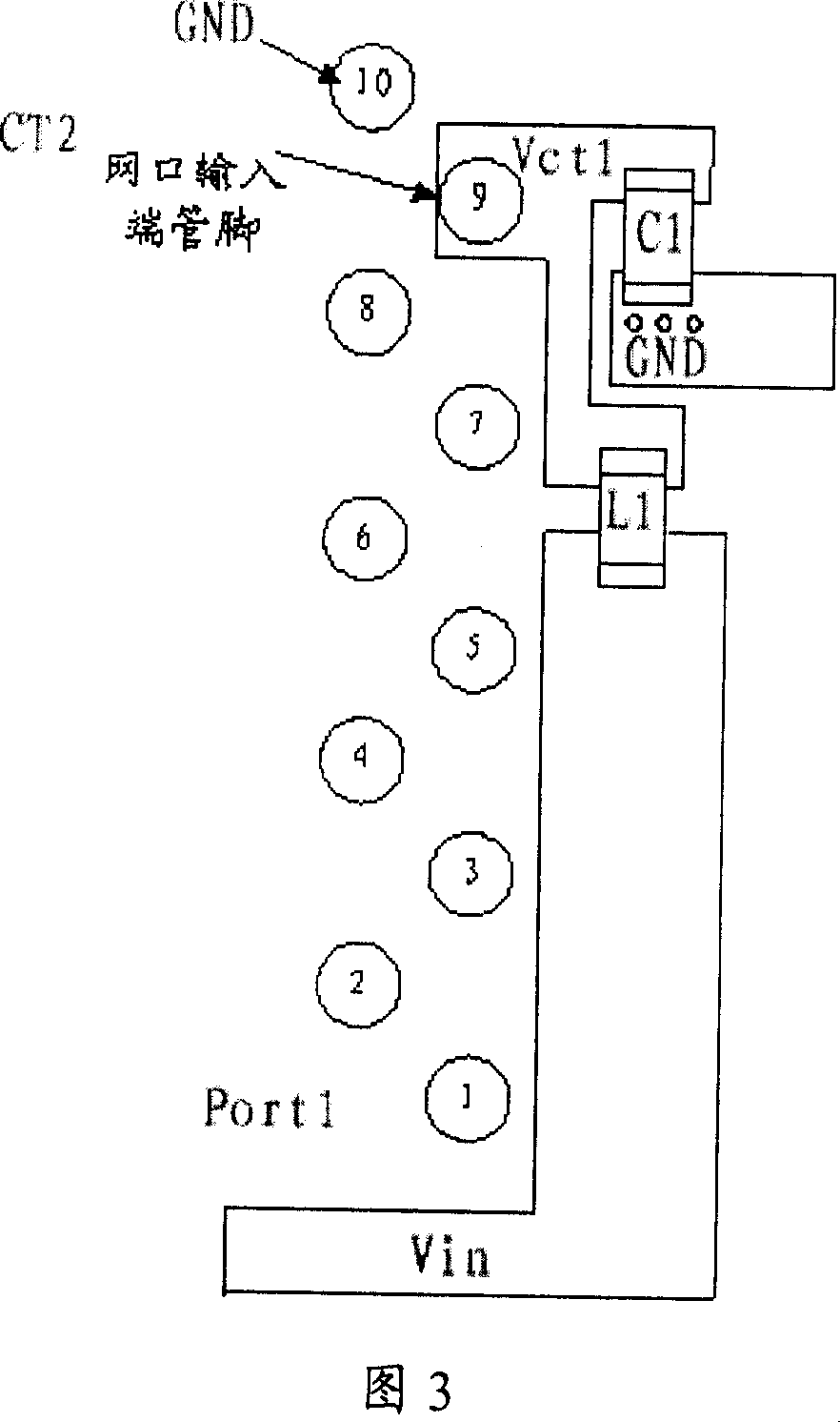
[0038] The first embodiment: Fig. 2 is the schematic diagram of the circuit of this embodiment.
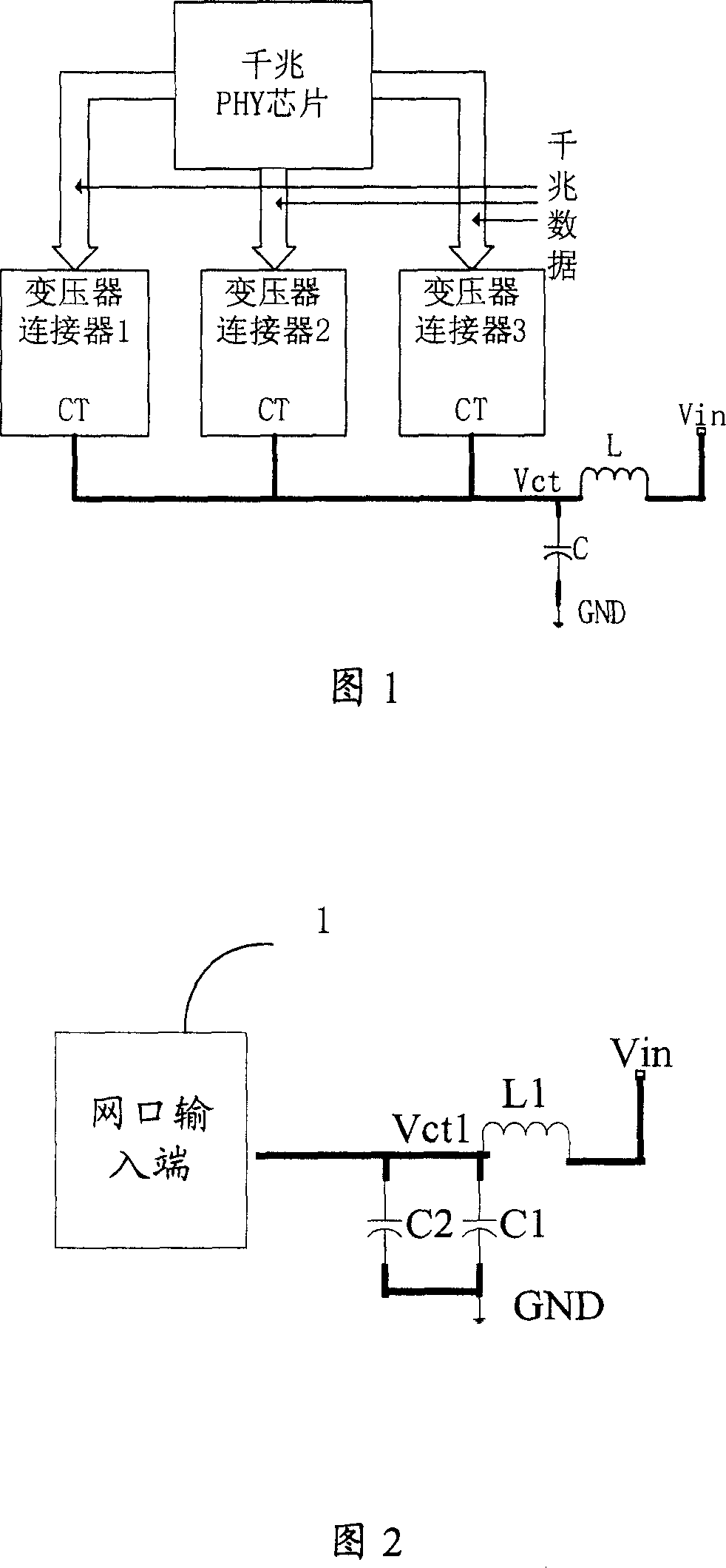
[0039] In Figure 2, 1 is the input port of the network port, the filter device includes magnetic beads L1 and capacitors C1 and C2, vin is the external power supply, and Vct1 is the power supply of the input port of the network port. C2 is the parasitic capacitance of the printed circuit board. One end of L1 is connected to the external power supply vin, the other end is connected to the input port of the network port together with C1 and C2, and the other end of C1 and C2 is connected to the ground.
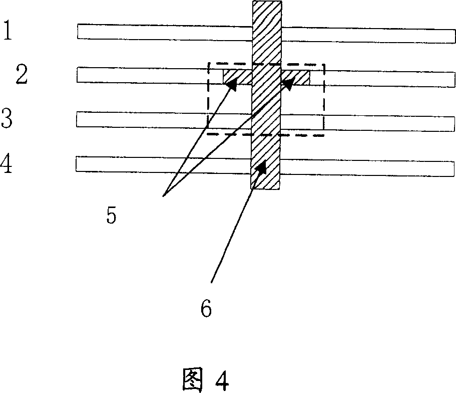
[0040]Figure 3 is the schematic diagram of the PCB design of the magnetic bead L1 and the capacitor C1. The network port has 10 pins, of which 1 to 8 are signal pins; pin 9 is the power input pin of the network port; pin 10 is the ground (GND) . The external power supply Vin is led from the bottom surface of the PCB to the Gigabit Ethernet port. After Vin is filtered by the filte...
no. 2 example
[0043] The second embodiment: In this embodiment, the case of one network port is described.
[0044] In this embodiment, the network port with filtering device includes a connector with an integrated transformer, a network port power input pin (ie, center tap CT), and a Gigabit Ethernet port composed of magnetic beads L, capacitor C1, and parasitic inductance C2 filter device; in the present invention, L adopts a magnetic bead with a rated DC freewheeling capacity greater than 150mA to meet the power demand of the center tap CT of the network port transformer. C1 can be used with 0.01u~0.1u surface-mounted ceramic capacitors, which can respectively supply power to the center tap of the corresponding network port transformer, and can also filter out the noise signal from the network port transformer or from Vin, the network port transformer and Vin are both Connected to C1, the noise generated by the network port transformer and Vin is filtered through the capacitor. The filt...
no. 3 example
[0049] The third embodiment: the network port circuit with multiple network ports in this embodiment is as shown in Figure 4:
[0050] In this embodiment, the network port with filtering device includes a connector with an integrated transformer, a network port power input pin (ie, center tap CT), and a Gigabit Ethernet port composed of magnetic beads, capacitors, and parasitic inductance C2 Filter device; each Gigabit Ethernet port has an independent filter circuit. As shown in Figure 5, L1, C1, and C2 form the filter circuit of Gigabit Ethernet port 1; L2, C3, and C4 form the filter circuit of Gigabit Ethernet port 2; L3, C5, and C6 form the filter circuit of Gigabit Ethernet port 2; The filter circuit of network port 3. These three sets of filter circuits are independent of each other and do not affect each other.
[0051] In this embodiment, L1, L2, and L3 use magnetic beads with a rated DC freewheeling capacity greater than 150mA to meet the power demand of the center t...
PUM
 Abstract
Description
Claims
Application Information
 - R&D
- Intellectual Property
- Life Sciences
- Materials
- Tech Scout
- Unparalleled Data Quality
- Higher Quality Content
- 60% Fewer Hallucinations
Browse by: Latest US Patents, China's latest patents, Technical Efficacy Thesaurus, Application Domain, Technology Topic, Popular Technical Reports.
© 2025 PatSnap. All rights reserved.Legal|Privacy policy|Modern Slavery Act Transparency Statement|Sitemap|About US| Contact US: help@patsnap.com