
Hot pipe

A heat pipe and pipe body technology, applied in the field of nanofluid heat pipes, can solve the problems of limited solubility and inability to effectively solve the problems of nanoparticle aggregation and deposition, and achieve the effect of preventing aggregation and deposition

Inactive Publication Date: 2008-03-26
HONG FU JIN PRECISION IND (SHENZHEN) CO LTD +1
View PDF3 Cites 0 Cited by
  • Summary
  • Abstract
  • Description
  • Claims
  • Application Information

AI Technical Summary

Problems solved by technology

However, the solubility of dispersants in the working liquid is limited and changes with temperature, which cannot effectively solve the problem of aggregation and deposition of nanoparticles

Method used


Image

  • Hot pipe
  • Hot pipe
  • Hot pipe

Examples


Embodiment Construction

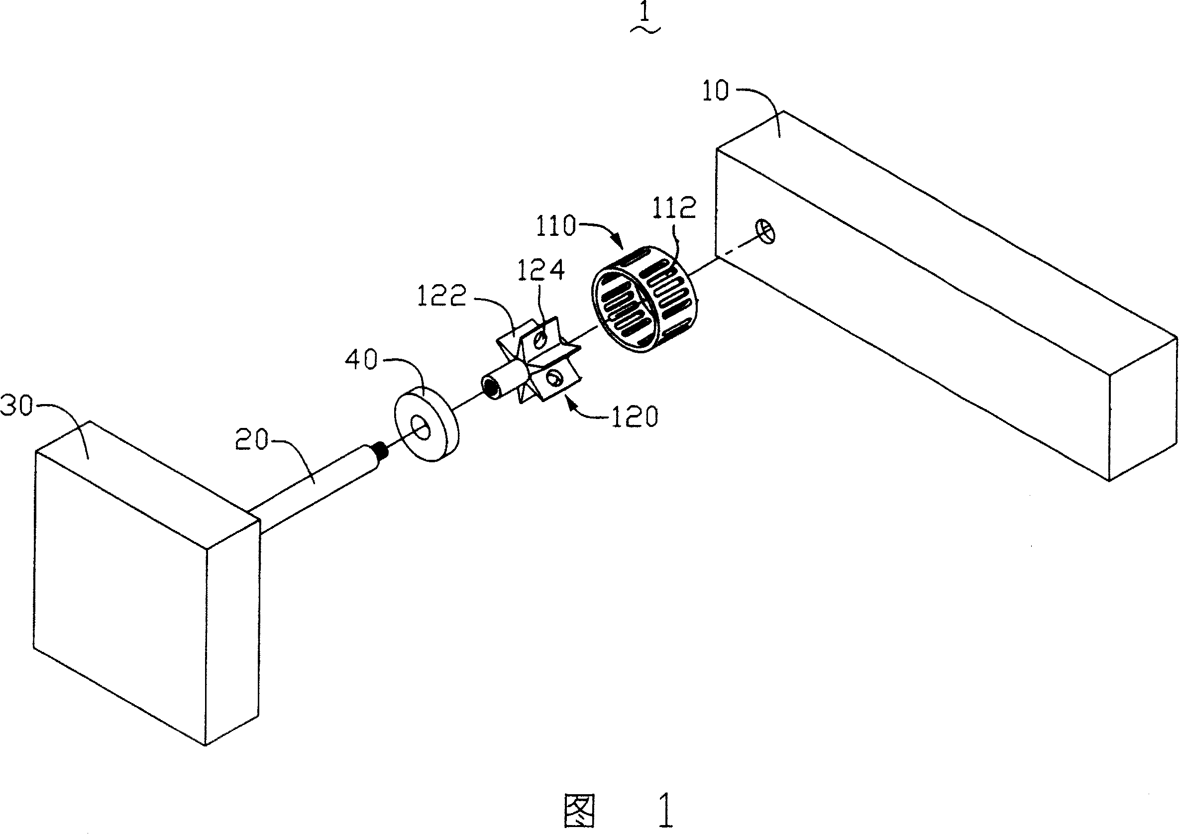
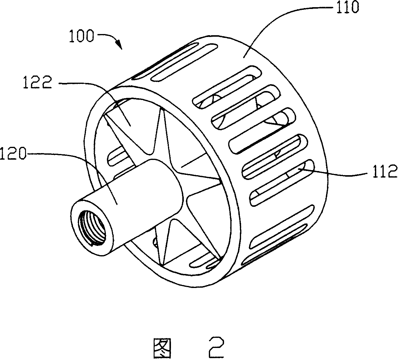
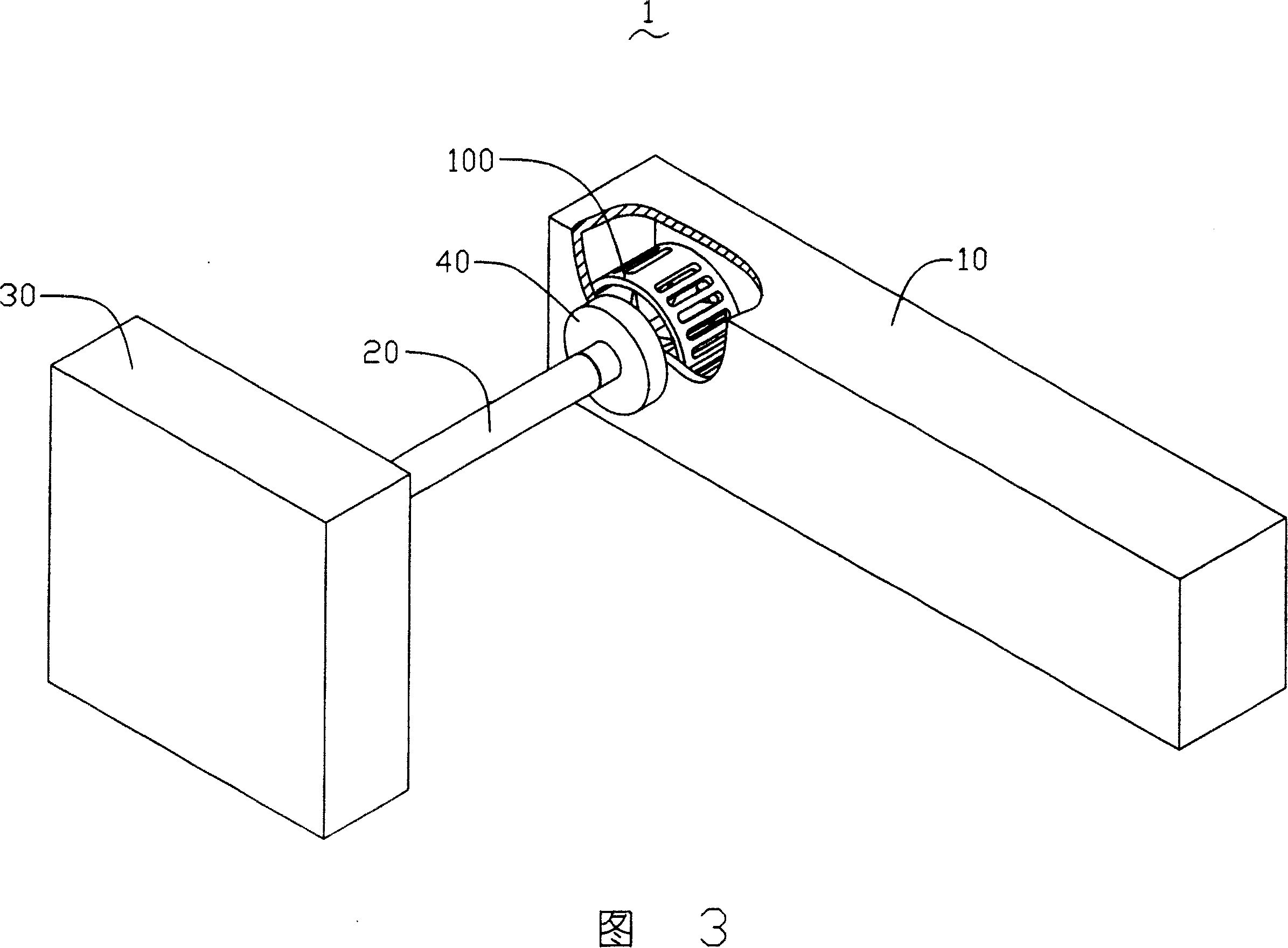
[0012] Please refer to FIG. 1 to FIG. 3 , the heat pipe 1 of the present invention includes a pipe body 10 , a transmission shaft 20 , a driving element 30 and a separation element 100 fixed in the pipe body 10 . The drive element 30 can be selected from a fan, a motor, and the like. The pipe body 10 includes a shell, a capillary structure close to the inner wall of the shell, and a working liquid. The working liquid is usually a liquid substance with a high heat of vaporization, good fluidity, stable chemical properties, and a low boiling point, such as water, ethanol, methanol, Acetone, etc., and adding nanoparticles such as nano-copper particles to the working fluid to improve the thermal conductivity of the working fluid. The capillary structure in the tube body 10 is best in groove type, but other structures such as powder sintering and wire mesh core are also acceptable because nanoparticles are added into the working liquid.

[0013] The transmission shaft 20 is used t...


PUM


Abstract

Disclosed a heat pipe, comprises a tube which including a housing and working liquid filled in this housing. Wherein, the working liquid contains nanometer particles; and the heat pipe comprises a clutching member in the housing and a driver to drive this clutching member. Said inventive heat pipe uses the driver to rotate the clutching member in the heat pipe, for the purpose that preventing the accumulation and deposition of nanometer particles.

Description

【Technical field】 [0001] The invention relates to a heat pipe, in particular to a nanofluid heat pipe applied to heat dissipation of electronic components. 【Background technique】 [0002] In order to ensure that the electronic components can work normally, it is necessary to dissipate the heat generated by the electronic components in time. The heat pipe is one of the commonly used heat dissipation devices. It uses the phase change of the internal working liquid to transfer heat. Therefore, the properties of the working liquid in the heat pipe, such as the heat transfer coefficient, have a great influence on the heat transfer performance of the heat pipe. [0003] In order to improve the properties of the working liquid and improve the performance of the heat pipe, people in the industry add nanofluids to the working liquid to make nanoparticle suspensions to enhance convection, resulting in better heat transfer characteristics than the original working liquid, such as addin...

Claims


Application Information

Patent Timeline
Patent Type & Authority Patents(China)
IPC IPC(8): H01L23/427H05K7/20F28D15/02
Inventor 颜士杰
Owner HONG FU JIN PRECISION IND (SHENZHEN) CO LTD
Learn More