Manually operated tool

A technology for processing equipment and fuel tanks, applied in metal processing equipment, sawing equipment, mechanical equipment, etc., can solve troublesome problems, achieve the effects of reducing the number of structural parts, simplifying manufacturing, and compacting the shell structure

Active Publication Date: 2008-04-02
ANDREAS STIHL AG & CO KG
View PDF4 Cites 2 Cited by
  • Summary
  • Abstract
  • Description
  • Claims
  • Application Information

AI Technical Summary

Problems solved by technology

Assembly is complex, since it must be noted that all connection points are sealed

Method used


Image

  • Manually operated tool
  • Manually operated tool
  • Manually operated tool

Examples


Embodiment Construction

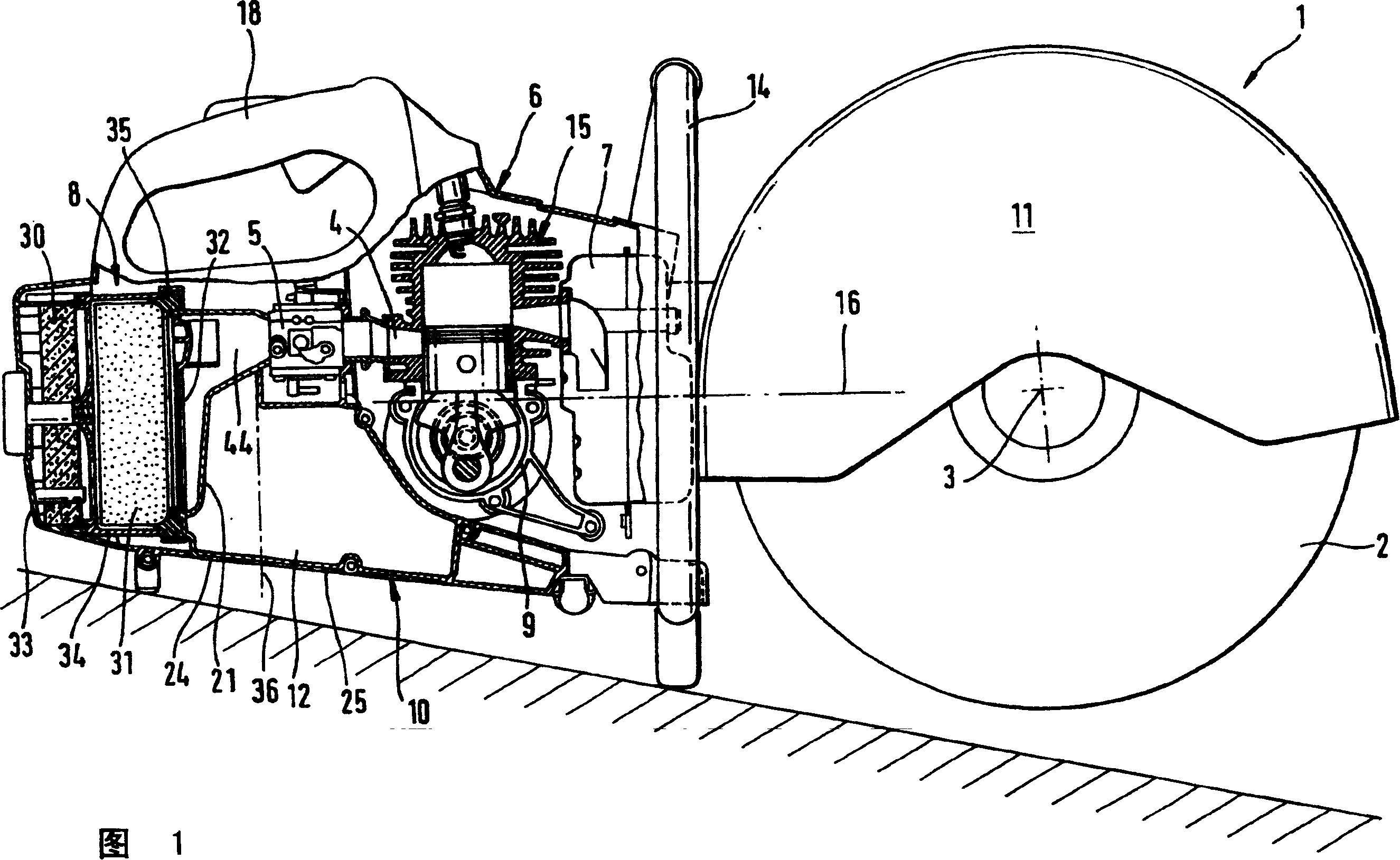
[0016] FIG. 1 shows a cutting machine 1 with a cutting blade 2 which is driven in rotation about an axis 3 . The cutting blade 2 is partially surrounded by a protective cover. The cutting machine 1 has a housing 6 in which a two-stroke motor 15 is arranged, which drives the cutting blade 3 via a belt (not shown). An exhaust muffler 7 is set on the outlet of the two-stroke engine. The two-stroke engine 15 supplies a fuel / air mixture via an intake channel 4 , which is processed in a carburetor 5 . The evaporator 5 is connected to the clean air side 44 of the air cleaning unit. The air cleaning unit comprises an air filter unit 8 having a pre-filter 30 arranged inside an end cap 33 , a main filter 31 inside an air filter housing 34 and a fine filter 32 . The air filter housing is closed by an air filter base plate 21 .

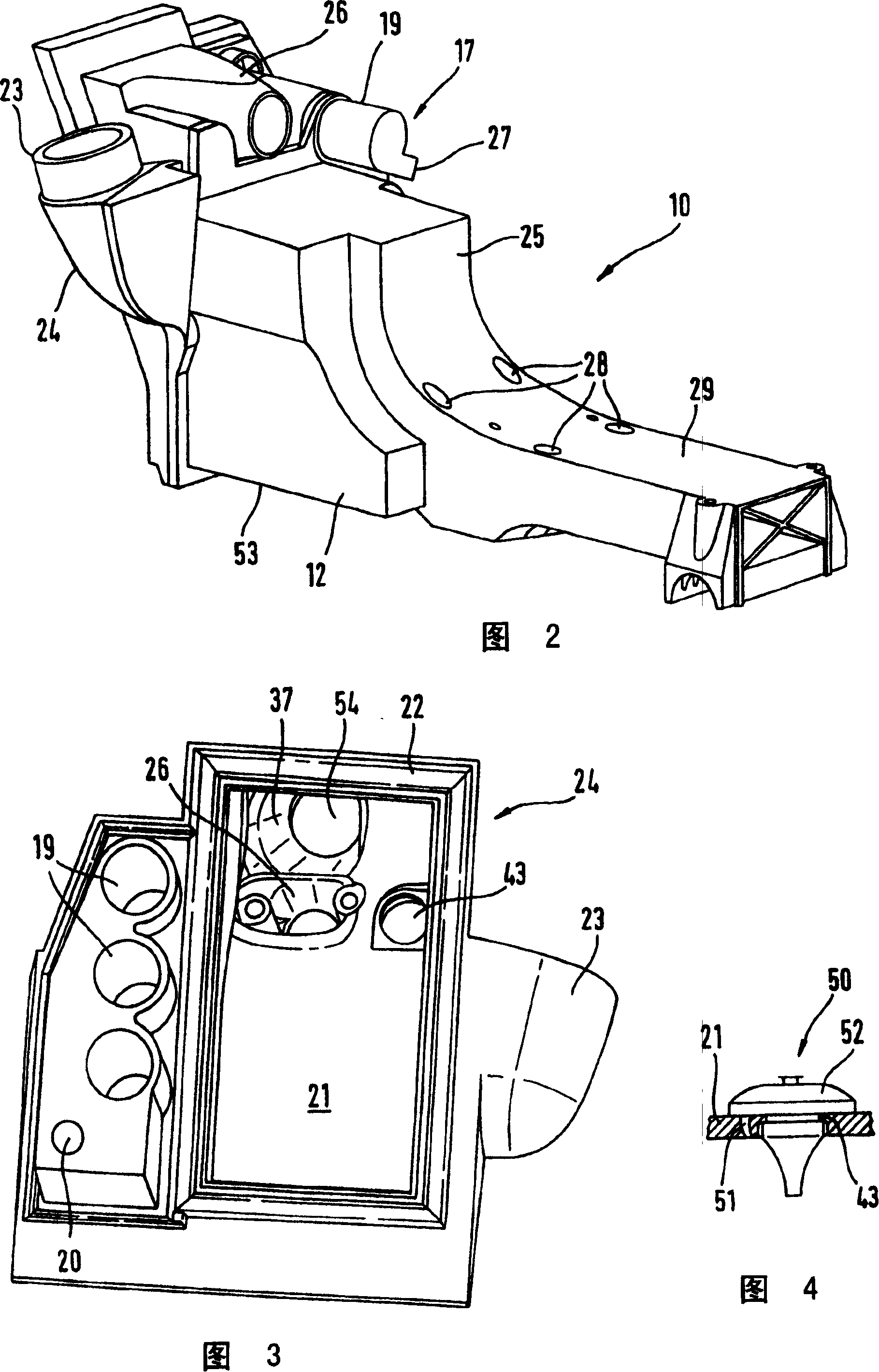
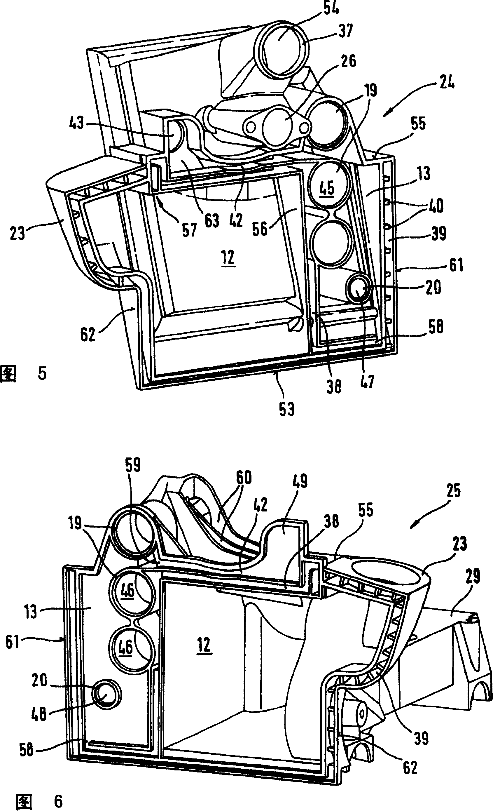
[0017] The cutting machine 1 has a fuel tank housing 10 which is arranged on an air filter base 21 . The fuel tank housing 10 is formed from two half shells...


PUM


Abstract

A manually operated tool such as a parting-off grinder, chainsaw or similar device has a tank housing which contains a fuel tank. The tool has an air cleaning unit, the tank housing being connected to the clean air side of the air cleaning unit via a bleed device. A simple design in which leaks are avoided results if a reservoir wall of the tank housing and a housing wall of the air cleaning unit are positioned adjacent to one another and the bleed device comprises a bleed opening which passes through the reservoir wall and the housing wall.

Description

technical field [0001] The present invention relates to hand-held processing equipment such as cutters, chainsaws and the like. Background technique [0002] A chainsaw is known from US 3,372,679, which has a fuel tank with a compensating container. The compensating container is connected by a tube to the carburetor housing, from which clean air is sucked in. Tubes extend outside the fuel tank housing and the carburetor housing. Leaks can develop in the fittings and in the tubes themselves, allowing fuel to escape. A complex seal is required to prevent leakage. Assembly is complex, since it must be noted that all connection points are sealed. Contents of the invention [0003] The object of the present invention is to realize a processing plant of the above-mentioned type in which fuel leakage is avoided. [0004] This object is achieved by a processing plant having the following characteristics. The handheld processing device has a fuel tank housing and an air clean...

Claims


Application Information

Patent Timeline
Patent Type & Authority Patents(China)
IPC IPC(8): B25F5/02B23D45/16B27B9/00F02M17/44F01N13/00F02B63/02F02M17/04F02M17/50F02M25/08F02M37/00
CPCF02M37/007Y10S220/905F02M37/0094F02M17/50F01N2590/06F02M37/0076F02B63/02F02M2025/0863F01N13/002F02M17/04F02M25/0854
Inventor K·-M·乌尔S·弗里德里希
Owner ANDREAS STIHL AG & CO KG
Why Eureka
Try Eureka