Float ball valve for supplying and draining oil in multifunctional sealed oil tank

A sealed oil tank, multi-functional technology, applied to multi-way valves, valve details, valve devices, etc., can solve the problems of large upward inclination angle of the connecting rod, increased friction of the valve core, and impossibility of oil discharge, so as to avoid installation errors , increase the effect of safety and simple structure

Active Publication Date: 2008-04-09
刘敬善
View PDF6 Cites 0 Cited by
  • Summary
  • Abstract
  • Description
  • Claims
  • Application Information

AI Technical Summary

Problems solved by technology

Although the structure and operating performance of the utility model pressure-stabilizing oil replenishment and discharge float valve are better than any other forms of oil replenishment and discharge devices for sealed oil tanks, some defects have also been found through operation experiments, and the defects are as follows: 1. The connecting rod is upward If the angle of inclination is too large, when the float rises to the highest point with the liquid level, the connecting rod is close to the vertical state, the torque is greatly reduced, and the force of falling back is reduced, and jamming may occur under special circumstances
2. The oil supply passage is controlled by the half annular groove on the circumference of the valve core, so the oil pressure from the oil supply system acts on the half annular groove to push the valve core to one side, increasing the friction of the valve core. The oil pressure of the oil supply system exceeds the rated oil pressure by a certain value, and the float rises to the highest point with the liquid level, that is, when the connecting rod is close to the vertical state, the valve core will be stuck and unable to move
4. The automatic oil discharge of the fuel tank is completed under the action of the hydrogen pressure connected between the fuel tank and the generator. When the generator is running at low hydrogen pressure, or when the gas is replaced and vacuumed, the oil discharge will not be realized. At this time, it can only be done by Manual adjustment is performed manually. At present, any automatic oil replenishment and oil discharge device cannot take into account the automatic oil discharge in this case.

Method used


Image

  • Float ball valve for supplying and draining oil in multifunctional sealed oil tank
  • Float ball valve for supplying and draining oil in multifunctional sealed oil tank
  • Float ball valve for supplying and draining oil in multifunctional sealed oil tank

Examples


Embodiment Construction

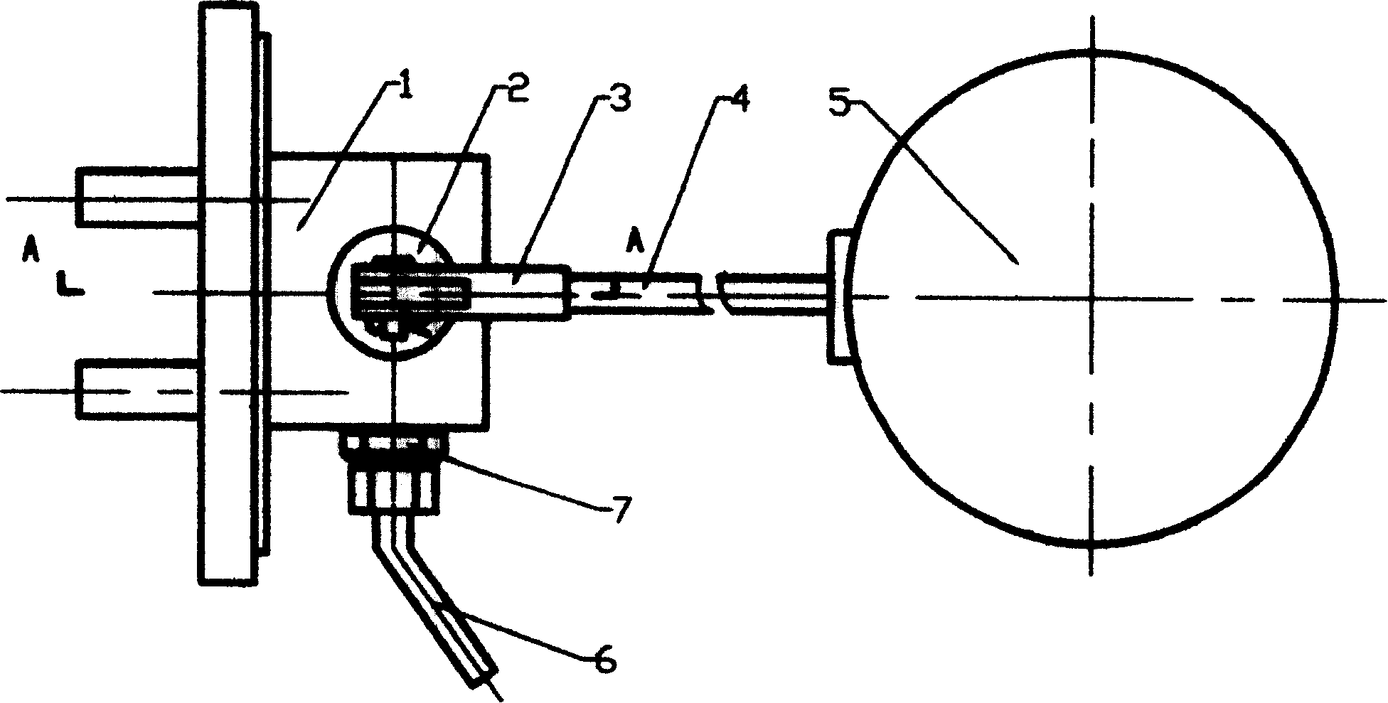
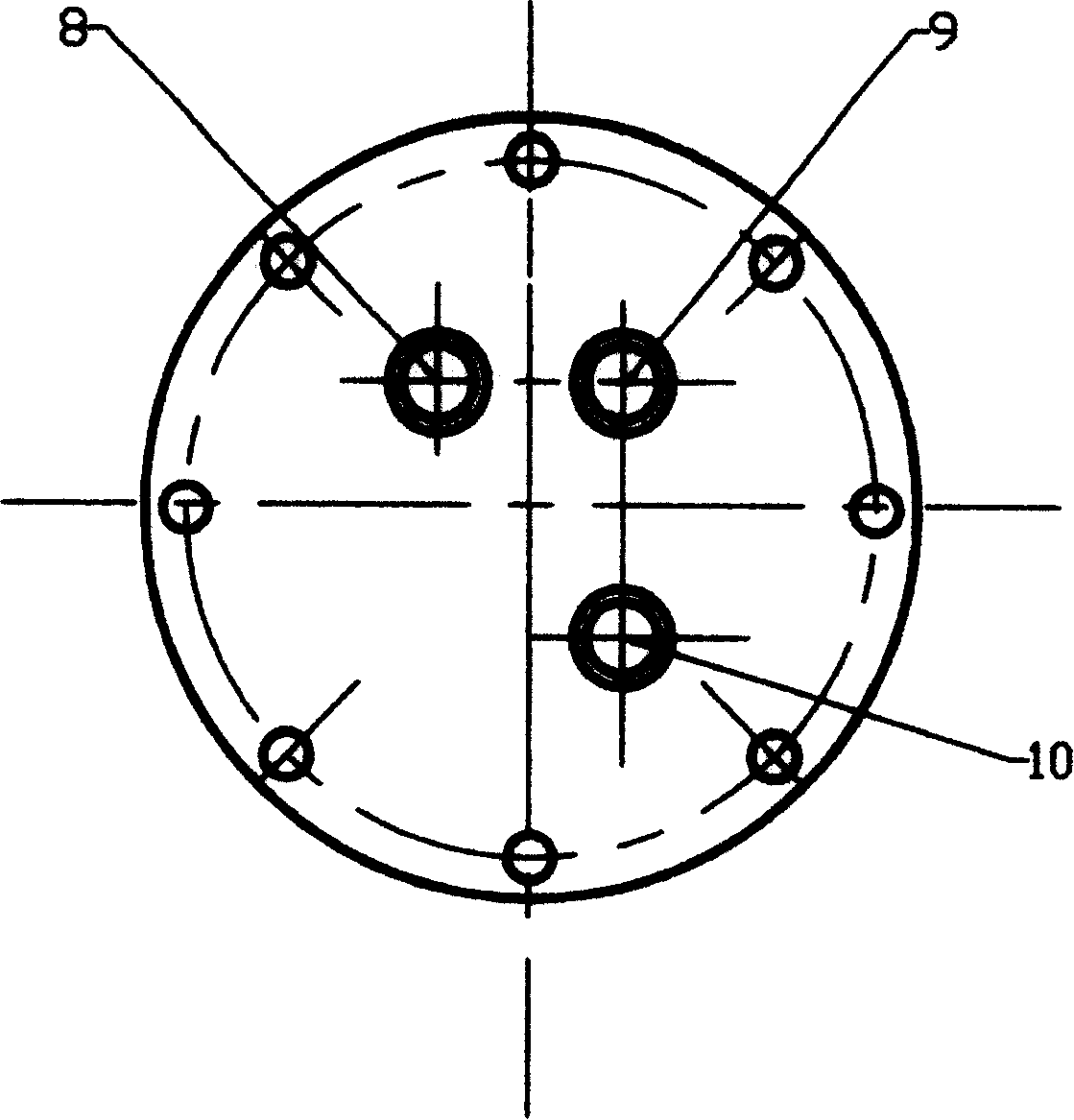
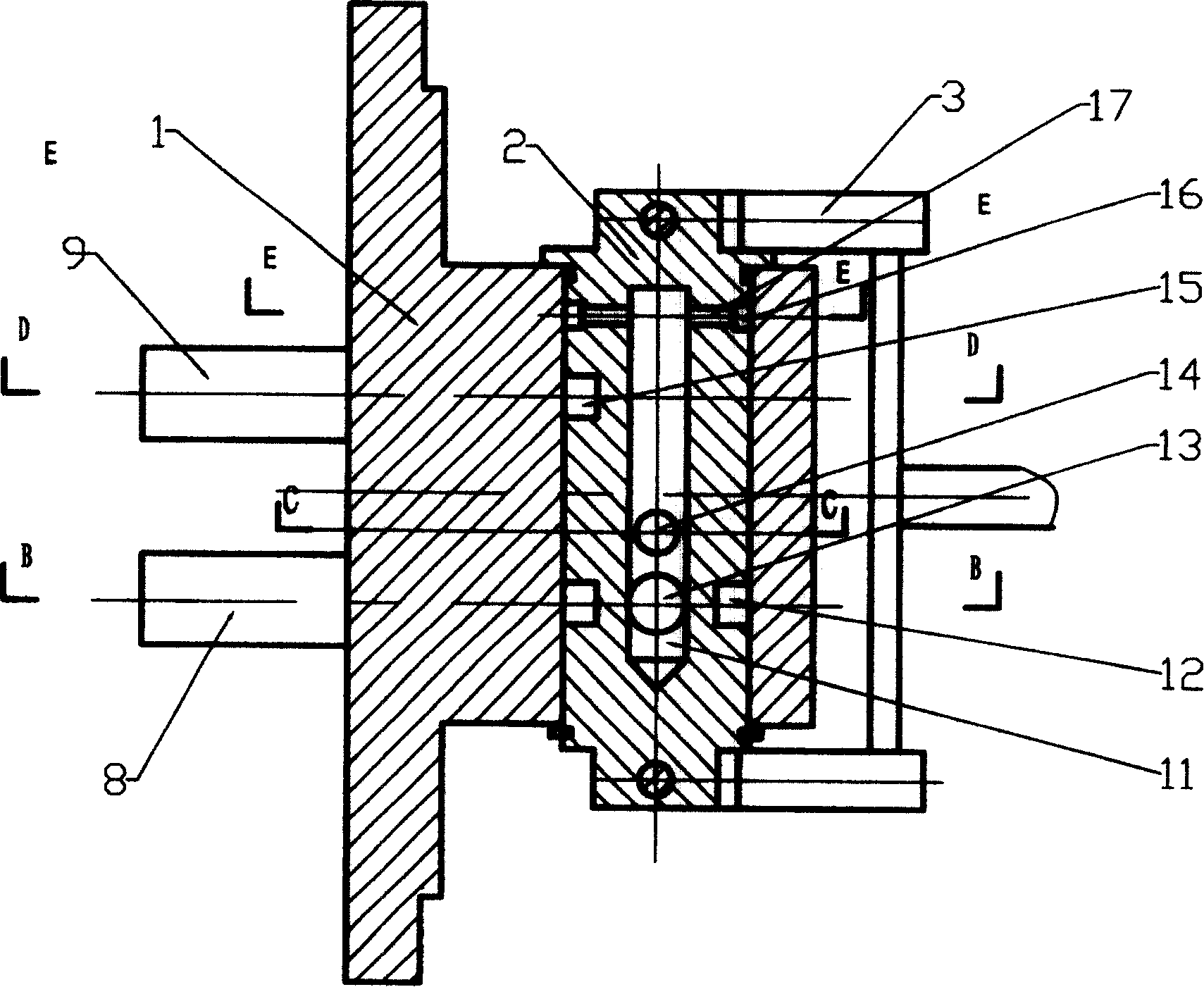
[0016] Such as Figure 1-6 As shown, a multi-functional sealed oil tank replenishment and discharge oil floating ball valve includes a valve body 1, a valve core 2, a connecting rod frame 3, a connecting rod 4, a floating ball 5, an oil discharge guide pipe 6, and a check door 7. It is characterized in that the left and right sides of the end face of the valve body 1 and the right side of the lower part are respectively provided with an oil supply pipe 8, an oil discharge pipe 9, and a power oil discharge pipe 10 (such as figure 2shown). Among them, the fuel supply pipe 8 is connected to the outlet of the oil pump of the airside fuel supply system, the oil discharge pipe 9 is connected to the main oil tank of the oil source of the airside fuel supply system, and the power oil discharge pipe 10 is connected to the outlet of the oil pump of the hydrogen side fuel supply system through an external valve. The inside of the valve body is provided with a second oil supply hole 18,...


PUM


Abstract

In the invention, a rotary valve consists of the valve body and the spool. A float is used for driving the spool to rotate in order to open and close oil-supply or oil-discharge channel and control the oil level of the oil tank via a connecting-rod and a connecting-rod rest. A check valve is used for changing the power oil-discharge and the pressure oil-discharge in the oil tank. At two ends of the spool are disposed two cannelures and an oil-supply system is used for forming sealed oilrings on the cannelures, so as to seal the clearance of the spool two ends.

Description

technical field [0001] The invention relates to an automatic oil replenishment and oil discharge device for a sealed oil tank in a double-flow annular shaft seal oil supply system of a power plant generator set, in particular to a multifunctional oil replenishment and discharge oil floating ball valve for the sealed oil tank. Background technique [0002] The multi-functional sealed oil tank supplementary discharge oil float valve is a new structure supplementary discharge valve redesigned on the basis of my original utility model patent for pressure-stabilized supplementary discharge oil float valve (patent application number: ZL 99 2 2522.1). Oil float valve. Although the structure and operating performance of the utility model pressure-stabilizing oil replenishment and discharge float valve are better than any other forms of oil replenishment and discharge devices for sealed oil tanks, some defects have also been found through operation experiments, and the defects are as...

Claims


Application Information

Patent Timeline
Patent Type & Authority Patents(China)
IPC IPC(8): F16K11/00F16K31/18
Inventor 刘敬善
Owner 刘敬善
Why Eureka
Try Eureka