
Unitized cage for cylindrical roller bearing

A technology of cylindrical rollers and cages, applied in the field of cages, can solve the problems of expensive manufacturing, lack of strength, and high manufacturing costs, and achieve the effect of simplifying mechanical components

Inactive Publication Date: 2008-04-16
THE TIMKEN CO
View PDF8 Cites 0 Cited by
  • Summary
  • Abstract
  • Description
  • Claims
  • Application Information

AI Technical Summary

Problems solved by technology

[0009] Other previous constructions use two pins without a machined divider, however, manufacturing with a welding operation of the pins is still expensive
Other previous structures required complex forming of metal sheets that may not have the strength to maintain their shape during harsh handling and were expensive to manufacture due to the complex shape

Method used


Image

  • Unitized cage for cylindrical roller bearing
  • Unitized cage for cylindrical roller bearing

Examples


Embodiment Construction

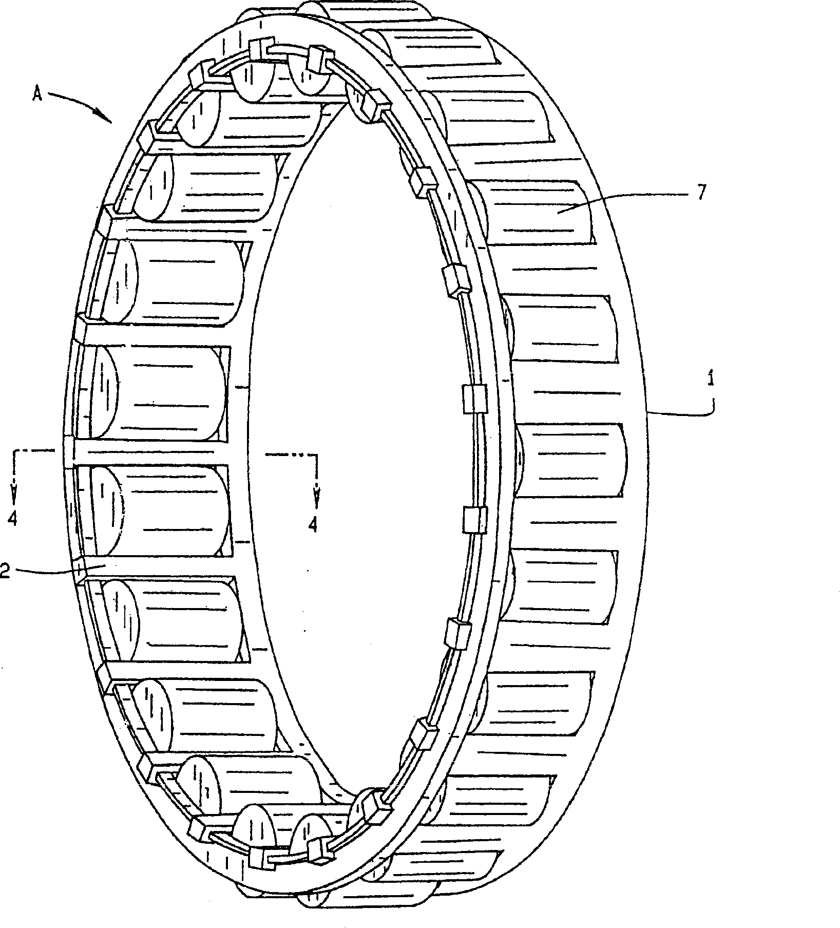
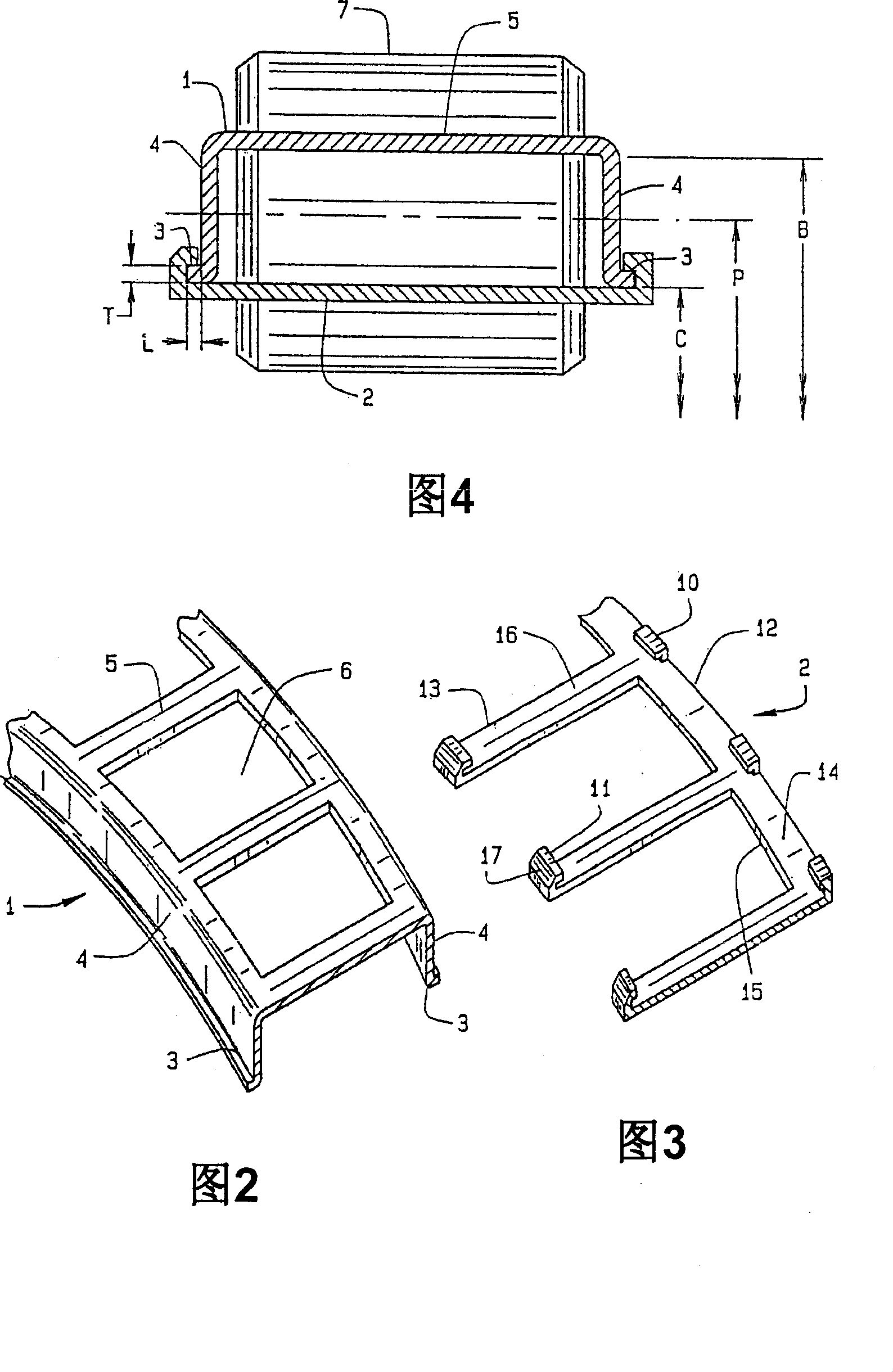
[0022] now refer to figure 1 , showing combined cage A. The composite cage A has a cage sleeve 1 and a cage ring 2 for containing and aligning a plurality of cylindrical rollers 7 . The cage sleeve 1 in FIG. 2 is formed as an annular ring with an X-axis and a generally hat-shaped cross-section. The hat shape is composed of two end face axial protrusions 3 with a length L and a thickness T, two end faces 4 and an upper part 5 . The two end faces 4 extend radially from the axis X and are generally perpendicular to the axial projections 3 of the end faces. In an alternative embodiment, the two end faces are generally not perpendicular to the axial protrusions 3 on the two end faces. The end faces 4 are connected together by an upper part 5 .

[0023] The upper part 5 has a plurality of cage grooves 6 dimensioned and arranged to allow the insertion of a plurality of cylindrical rollers 7 . Such shape and size of the plurality of cage grooves 6 allows free rotation of the cyli...


PUM


Abstract

A unitized cage (A) for cylindrical roller bearings wherein the inner raceway of the bearing configuration may be the rotating or stationary shaft component and the outer raceway of the bearing configuration may be the rotating or stationary housing component. Thus, a bearing configuration can be generated without the need for a separate inner or outer race having inner or outer raceways. The unitized cage (A) comprises a cage nest (1) having end face axial projections (3) and a cage finger ring (2) having fingers (11) which engage the end face axial projections (3) to lock the cage nest (1) into position on the cage finger ring (2). A plurality of cylindrical rollers (7) can be positioned within the cage pockets (6) of the cage nest (1) prior to the assembly of the cage nest (1) with the cage finger ring (2) to generate a cylindrical roller bearing.

Description

[0001] Cross References to Related Applications [0002] This application is related to, and claims priority from, US Nonprovisional Patent Application No. 10 / 199,264, filed July 19, 2002. technical field [0003] The present invention relates generally to a cage for a roller bearing, and more particularly, to a composite cage for a cylindrical roller bearing. Background technique [0004] In applications where the bearing shaft and housing can be hardened and polished to roller bearing specifications, the use of cylindrical rollers without inner and outer rings can reduce profile height and weight requirements for power transmission components. In such applications, the inner and outer rings are not required because the bearing races normally found in the inner and outer rings are now seated on the surface of the shaft or housing for the bearing. [0005] A typical application for this configuration is a heavy industrial planetary gearbox, where the planet pins and gear bo...

Claims


Application Information

Patent Timeline
Patent Type & Authority Patents(China)
IPC IPC(8): F16C33/46F16C19/26F16C33/54F16C33/56
CPCF16C33/4611F16C33/547F16C33/4652F16C2226/74F16C19/26F16C2361/61Y10T29/49687Y10T29/49686
Inventor M·N·考特扎拉斯P·M·利内特R·E·小史密斯
Owner THE TIMKEN CO
Learn More