Calliper brake with disengaged position

A caliper brake, brake technology, applied in the direction of brake type, automatic brake, axial brake, etc.

Active Publication Date: 2008-04-30
CHRISTIAN MAYR GMBH & CO KG
View PDF4 Cites 6 Cited by
  • Summary
  • Abstract
  • Description
  • Claims
  • Application Information

AI Technical Summary

Problems solved by technology

Even if the brake disc is produced with high precision and has a good support device, there will be grinding noise here

Method used


Image

  • Calliper brake with disengaged position
  • Calliper brake with disengaged position
  • Calliper brake with disengaged position

Examples


Embodiment Construction
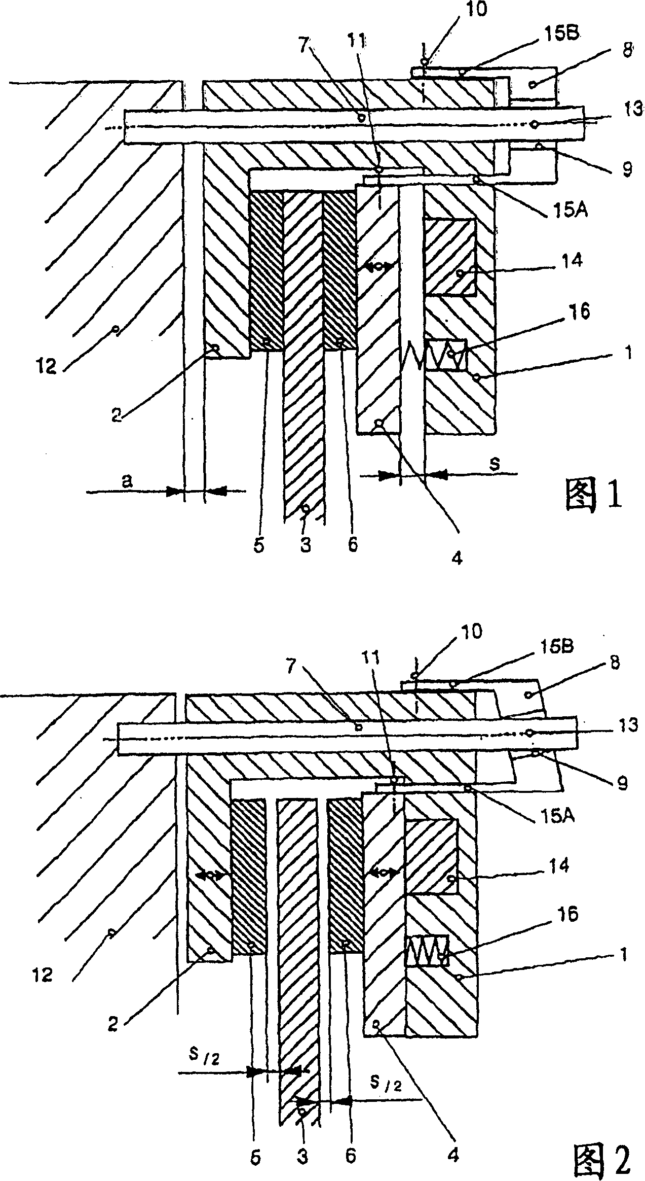
[0018] The basic idea of ​​the invention is to convert the movement of the armature relative to the coil carrier into a counter-movement of the coil carrier and therefore also of the opposite friction surface on the caliper side, since it is fixed to the coil carrier connected. The respective initial position of the armature disk is adjusted by frictional engagement of the pivot lever 8 on the fixed guide pin 7 .

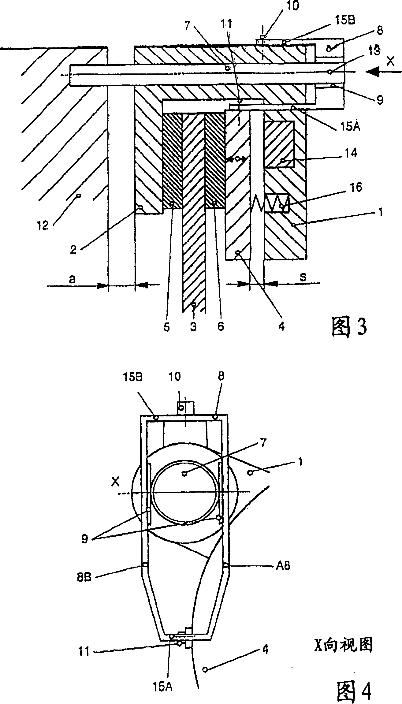
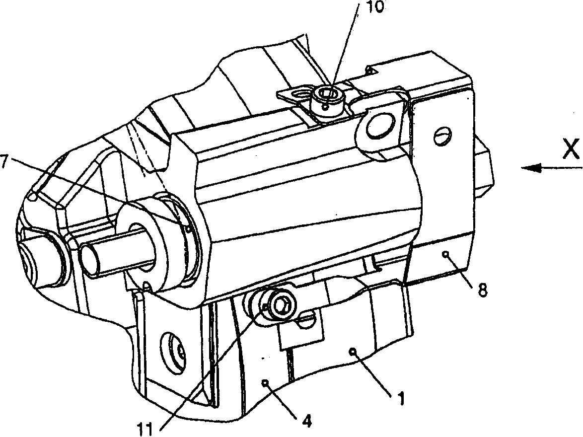
[0019] The swing lever 8 is a formed part made of a spring steel strip, with two opposite arms 8A, 8B, which abut on both sides of the fixed pin 7, and are provided with a friction plate 9 on its inner surface, so that As shown in FIG. 4 , the swing rod is fixed on the fixed pin shaft 7 in a frictional engagement manner. The amount of elastic deformation and the friction plate determine the axial friction force on the guide pin shaft. The rocker has two opposing flexible tongues 15A and 15B, of which one tongue 15A is connected to the armature disk 4 and the other...


PUM


Abstract

The invention relates to a calliper brake for a brake disc, in particular for elevator drives. Said brake comprises a brake body that is mounted on a fixed bolt (7) in a floating manner (1) and a brake calliper (2) that impinges on the brake disc (3) from the outer periphery of the latter, in addition to a solenoid (14) that is integrated into the brake body (1) to electromagnetically pull a spring-loaded armature disc (4) against the brake body (1). Said armature disc (4) and the section of the brake calliper (2) lying axially opposite are equipped with friction linings (5, 6) for engaging with the two end faces of the brake disc (3). To release or centre the calliper brake in relation to the brake disc at any time, a dual-arm rocker lever or bracket (8) is pivotally mounted on the fixed bolt, one limb (15B) of said lever or bracket being connected to the peripheral surface of the armature disc (4) and the other limb (15A) to the brake calliper, in such a way that the rocker lever or bracket (8) displaces the armature disc (4) when the brake is disengaged, simultaneously redirecting said movement into a displacement of the brake calliper (2) in the opposite direction, in order to obtain an air gap (s / 2) on both sides of the brake disc (3).

Description

【Technical field】 [0001] The invention relates to a caliper brake, which surrounds the periphery of a brake disc to be braked from both sides and is pressed against the corresponding end surface of the brake disc by means of friction plates during braking. In caliper brakes of this type, the brake body must be supported in a floating manner so that the so-called brake caliper can adapt to the position of the brake disc when the friction linings wear. 【Background technique】 [0002] The caliper brake proposed by the applicant has a free-floating support device and belongs to the prior art. In a specific implementation, the customer may find that friction noise sometimes occurs due to the friction between the friction lining and the brake disc. This grinding noise may be undesirable. [0003] One solution to this problem is to adjust the air gap of the friction surface on the side of the brake caliper via three bolts and to adjust the pressing force of the brake on these bol...

Claims


Application Information

Patent Timeline
Patent Type & Authority Patents(China)
IPC IPC(8): F16D59/02F16D65/54F16D55/226F16D65/14
CPCF16D65/54F16D2121/22F16D55/226F16D2127/02
Inventor K·艾班德
Owner CHRISTIAN MAYR GMBH & CO KG
Why Eureka
Try Eureka