Compressor and manufacturing method thereof

A manufacturing method and compressor technology, which is applied to mechanical equipment, machines/engines, liquid fuel engines, etc., can solve the problems of uneven force on the stator and rotor, loud noise, etc., to reduce welding deformation, reduce offset, The effect of machine noise improvement

Active Publication Date: 2019-03-05
SHANGHAI HITACHI ELECTRICAL APPLIANCES CO LTD
View PDF9 Cites 4 Cited by
  • Summary
  • Abstract
  • Description
  • Claims
  • Application Information

AI Technical Summary

Problems solved by technology

The inventors have found through research that such a structure and assembly method has the following disadvantages: welding deformation and rotor 22' offset will inevitably occur during the assembly process, and the offset of the air gap of the stator and rotor 22' cannot be fundamentally avoided.
The air gap between the stator 21' and the rotor 22' is uneven, which may cause collision between the rotor 22' and the stator 21', making the force on the stator and rotor more uneven, which will generate greater noise

Method used


Image

  • Compressor and manufacturing method thereof
  • Compressor and manufacturing method thereof
  • Compressor and manufacturing method thereof

Examples


no. 1 example

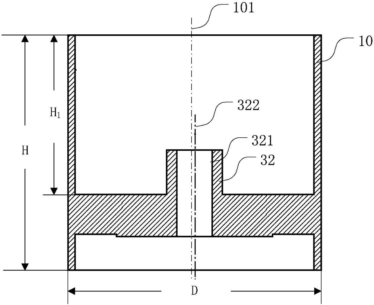
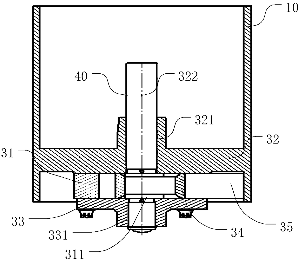
[0054] like Figure 2 to Figure 4 , figure 2 It is a sectional view of the integration of the casing and the upper cylinder head according to the first embodiment of the present invention; image 3 It is a cross-sectional view of the internal assembly of the compressor housing of the first embodiment of the present invention; Figure 4 It is a sectional view of the crankshaft in the first embodiment of the present invention.

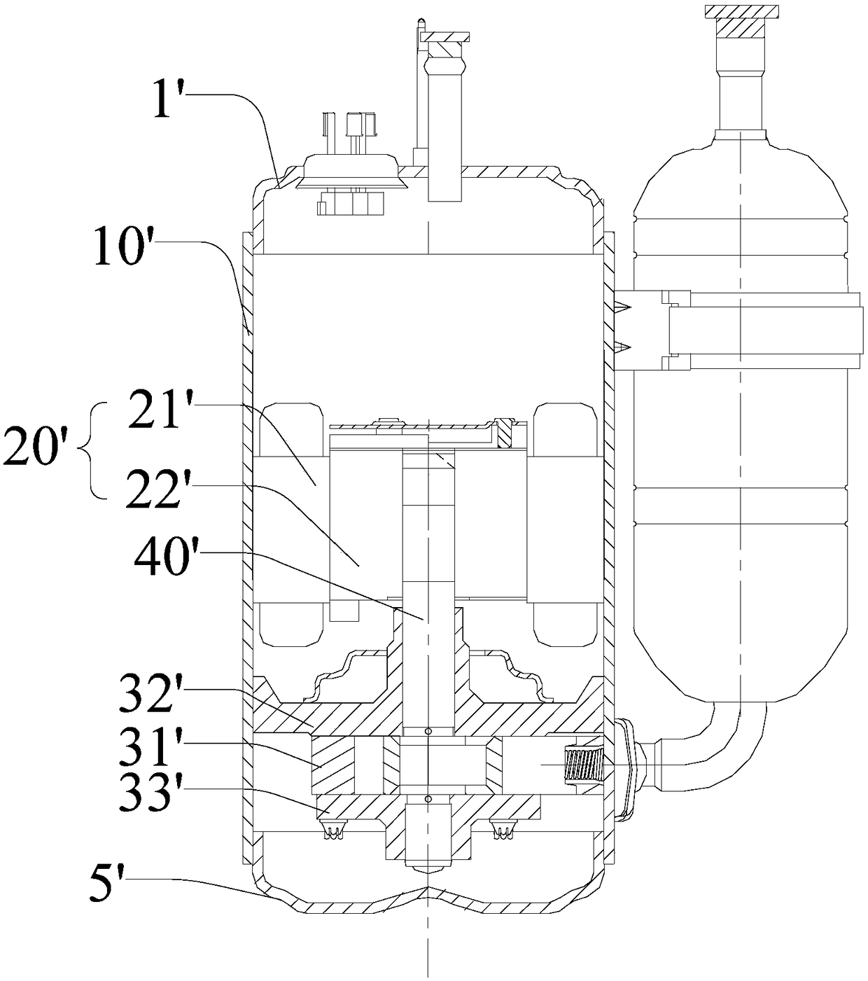
[0055] Compressor comprises housing 10, upper cylinder cover 32, lower cylinder cover 33, motor (as figure 1 Middle mark 20 '), cylinder 31, crankshaft 40. The casing 10 has an accommodating space. The housing 10 is optionally a cylindrical shell with a central axis 101 . The ratio H / D of the height H of the housing 10 on the central axis 101 to the outer diameter D of the housing 10 is greater than or equal to 0.3. In the vertical compressor embodiment, since the components are connected axially, the housing 10 needs to have sufficient height to ac...

no. 2 example

[0061] see Figure 5 , Figure 5 It is a cross-sectional view of the internal assembly of the compressor housing when the housing and the cylinder are integrated in the second embodiment of the present invention.

[0062] Compressor comprises housing 10, upper cylinder cover 32, lower cylinder cover 33, motor (as figure 1 Middle mark 20 '), cylinder 31, crankshaft 40. The casing 10 has an accommodating space. The upper cylinder head 32 is located in the casing 10 and has a first inner hole 321 with an axis 322 parallel to the central axis 101 .

[0063] The lower cylinder cover 33 is located in the casing 10 , and the lower cylinder cover 33 has a second inner hole 331 coaxial with the first inner hole 321 . The motor and cylinder 31 are accommodated in the casing 10 . The cylinder 31 has a third inner hole 311 whose axis is parallel to the central axis 101 . The crankshaft 40 is inserted into the upper first inner hole 321 , the third inner hole 311 and the second inner...


PUM


Abstract

The invention provides a compressor and a manufacturing method thereof. The compressor comprises a shell, an upper cylinder cover, a lower cylinder cover, a motor, an air cylinder and a crankshaft; the shell is provided with a central shaft; the upper cylinder cover is located in the shell and provided with a first inner hole which is axially parallel to the central shaft; the lower cylinder coveris located in the shell and provided with a second inner hole coaxial with the first inner hole; the motor and the air cylinder are contained in the shell, and the air cylinder is provided with a third inner hole which is axially parallel to the central shaft; the crankshaft is used for transmitting rotating force of the motor to a piston of the air cylinder to compress a refrigerating agent, andthe crankshaft is inserted into the first inner hole, the third inner hole and the second inner hole; and before the crankshaft is inserted into the first inner hole, the upper cylinder cover or theair cylinder and the shell are an integrated part, or the upper cylinder cover or the air cylinder and the shell are connected with each other. According to the compressor and the manufacturing methodthereof, noise of the compressor can be reduced.

Description

technical field [0001] The invention relates to the field of air conditioners, in particular to a compressor and a manufacturing method thereof. Background technique [0002] In general, a hermetic compressor includes a motor for generating a driving force in an inner space of a hermetically sealed case, and a compression part coupled to the motor for compressing refrigerant. Rolling rotor compressors are mainly used in air conditioners, refrigerators, communication base stations and other related refrigeration and air conditioning fields. The compression principle of the rolling rotor compressor mainly utilizes the rotational force of the motor. [0003] The motor of the scrolling rotor compressor in the prior art has a crankshaft through which the rotational force of the motor is transmitted to the compression components. For example, if figure 1 As shown, the main structure of the rotary hermetic compressor is as follows: [0004] The upper and lower ends of the seale...

Claims


Application Information

Patent Timeline
Patent Type & Authority Applications(China)
IPC IPC(8): F04B35/04F04B39/14F04B39/00
CPCF04B35/04F04B39/0027F04B39/14F04B39/00F04C29/00
Inventor 沈建芳周易赵凤荣王海军
Owner SHANGHAI HITACHI ELECTRICAL APPLIANCES CO LTD
Why Eureka
Try Eureka