
Three-dimensional imaging method employing area array projection self-synchronous optical path rotation

A 3D imaging and self-synchronization technology, applied in the imaging field, can solve the problems of low 3D imaging resolution, high system cost, and low imaging efficiency, and achieve the effects of improving 3D imaging accuracy, improving control accuracy, and increasing the field of view

Inactive Publication Date: 2008-04-30
SHANGHAI JIAOTONG UNIV
View PDF5 Cites 0 Cited by
  • Summary
  • Abstract
  • Description
  • Claims
  • Application Information

AI Technical Summary

Problems solved by technology

However, in order to achieve large-scale 3D imaging with optical path rotation, the following methods are usually used and have their own problems: (1) The self-synchronized scanning 3D imaging technology based on point laser projection is adopted. Since the method of point projection is adopted, The imaging efficiency is very low, and when the imaging efficiency is required to be improved, the system cost will become very high; (2) The synchronous scanning 3D imaging technology based on line laser projection is adopted, and the imaging efficiency is also low due to the line projection method. When it is required to improve the imaging efficiency, the system cost will become very high; (3) Using the synchronous scanning 3D imaging technology based on multi-laser sheet projection, there are projected light stripes that cannot be coded, and the computer recognizes and distinguishes the deformed projected light stripes there are great difficulties
[0003] After searching the literature of the prior art, it was found that the invention patent of Chinese Patent Publication (Notice) No. CN1737642 "Method for synchronously scanning binocular vision three-dimensional imaging based on area array projection", although the synchronous scanning method of area array projection was adopted, but In practical applications, it is found that due to the large moment of inertia of the swing mirror, there is inevitably a gap between the transmission connection between the motor and the swing mirror shaft, the control of the rotation angle is difficult, and the three-dimensional imaging accuracy is low; , there is an unstable period at both ends, so these two parts of data often need to be eliminated; moreover, the field of view covered by both ends of the effective field of view of 3D imaging cannot achieve the goal of cumulative subdivision, so the 3D imaging method along the measured object The 3D imaging resolution at both ends of the longitudinal field of view is low, that is, the resolution of 3D imaging with a large viewing angle is uneven; in addition, this method can only achieve a large viewing angle in one direction, and has not yet achieved 3D imaging with a large field of view

Method used


Image

  • Three-dimensional imaging method employing area array projection self-synchronous optical path rotation
  • Three-dimensional imaging method employing area array projection self-synchronous optical path rotation

Examples


Embodiment Construction

[0012] In order to better understand the technical solutions of the present invention, a further detailed description will be made below in conjunction with the accompanying drawings and implementation examples.

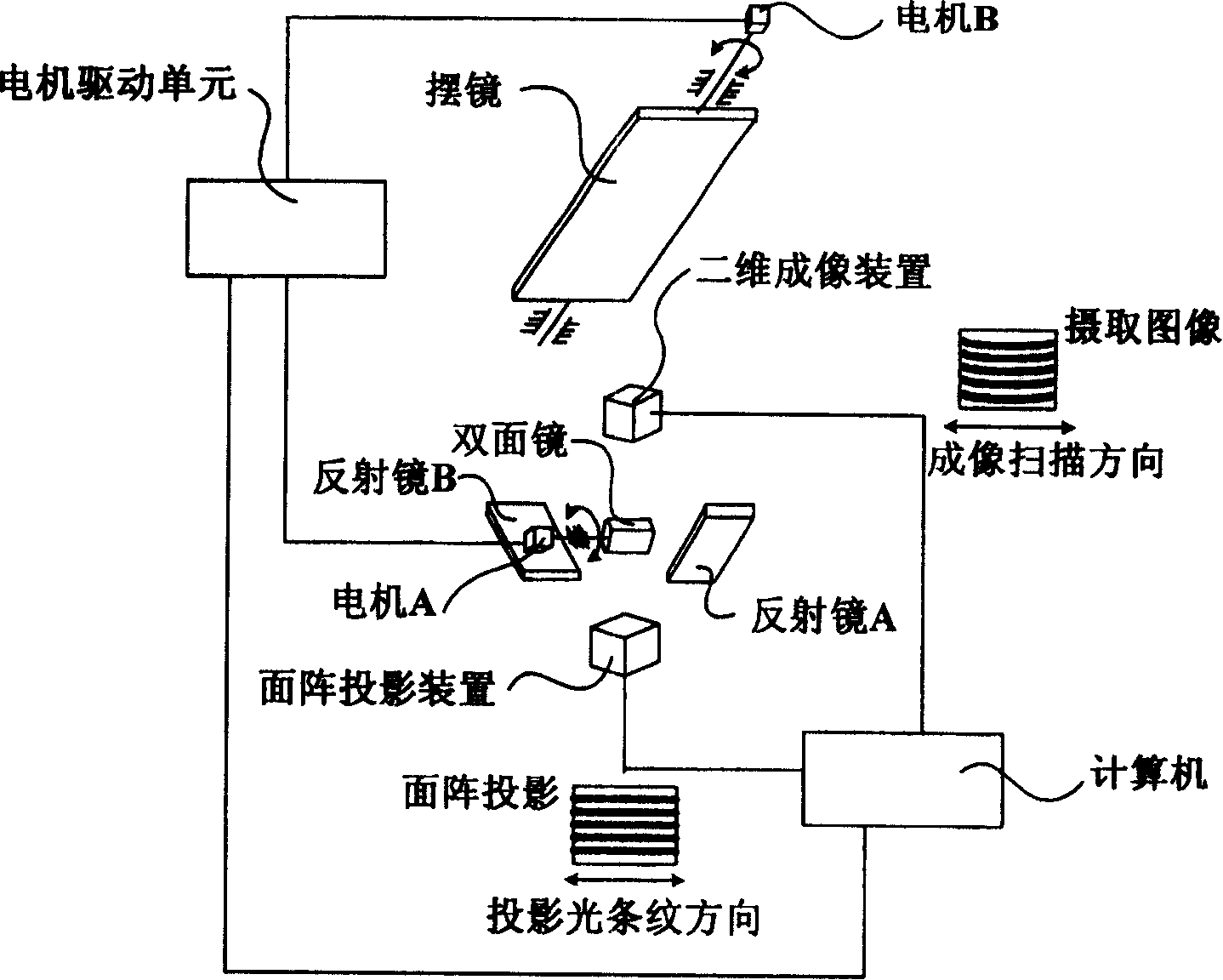
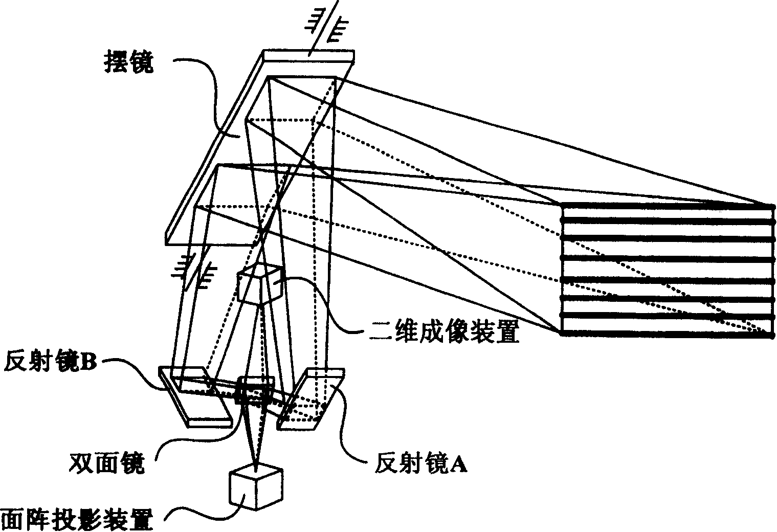
[0013] Such as figure 1 , figure 2 As shown, the area array projection device is facing the two-dimensional imaging device, and there is a double-sided mirror controlled by the first motor A to rotate between the two. The extension direction of the area array projection stripes emitted by the area array projection device, the horizontal scanning direction of the two-dimensional imaging device and the rotation centerline of the double-sided mirror are in the same direction. The area array projection device in the present invention is a common area array projection device, such as a liquid crystal projector, etc., and its projection mode adopts any existing two-dimensional area array projection light technology with coded information, such as grating projection, Four...


PUM


Abstract

The invention discloses a method for surface array project self-synchronous optical path rotate three-dimensional image, which uses the surface array project self-synchronous optical path rotate technique. Wherein, the project light stripe direction of surface projector, the image scanning direction of two-dimension imager and the rotate central line of dual-surface glass are same; via the rotation and reflection of dual-surface glass and swing glass, several local effective visual fields formed by intercrossing the projection optical path of surface array projector and the receiving path of two-dimension imager; in said local effective visual field, it can meet the condition to avoid image moving fuzzy when the two-dimension imager picks image; and using optical imaging, it can attain the three-dimension image data of said several local effective visual filed, to be accumulated to attaint the data of large visual field three-dimension image. The invention via rotating and moving local effective visual field, realize the large visual field three-dimension image on the tested object, which can be used to produce large visual field surface array sensor with lower cost, small volume and high property.

Description

technical field [0001] The invention relates to an imaging method in the field of optical technology, in particular to a three-dimensional imaging method for area array projection self-synchronized optical path rotation. Background technique [0002] The optical three-dimensional imaging technology based on optical path rotation has a wide range of application backgrounds because it can perform non-invasive three-dimensional imaging on larger targets at a relatively short distance. However, in order to achieve large-scale 3D imaging with optical path rotation, the following methods are usually used and have their own problems: (1) The self-synchronized scanning 3D imaging technology based on point laser projection is adopted. Since the method of point projection is adopted, The imaging efficiency is very low, and when the imaging efficiency is required to be improved, the system cost will become very high; (2) The synchronous scanning 3D imaging technology based on line lase...

Claims


Application Information

Patent Timeline
Patent Type & Authority Patents(China)
IPC IPC(8): G02B27/22G02B27/18G06T17/00
Inventor 陈亚珠程胜
Owner SHANGHAI JIAOTONG UNIV
Learn More