Fiber collecting mechanism for automatic optical fiber winding machine

A technology of optical fiber ring winding machine and driving mechanism, which is applied in the direction of light guides, optics, optical components, etc., can solve the problems of inaccurate counting and no delay, and achieve the effect of uniform fiber ring, no delay and space saving

Inactive Publication Date: 2008-05-21
BEIHANG UNIV
View PDF5 Cites 0 Cited by
  • Summary
  • Abstract
  • Description
  • Claims
  • Application Information

AI Technical Summary

Problems solved by technology

[0007] The advantages of the fiber receiving mechanism of the present invention are: (1) the position between the driving part and the sliding part can be adjusted arbitrarily; (2) the driving part and the sliding part adopt a separate design, which is beneficial to save the use space of the working table of the optical fiber winding machine ;(3) The automatic counting of the driving part solves the inaccurate defect of manual winding fiber counting, and at the same time makes the wound fiber ring uniform; Products such as micro force winding

Method used


Image

  • Fiber collecting mechanism for automatic optical fiber winding machine
  • Fiber collecting mechanism for automatic optical fiber winding machine
  • Fiber collecting mechanism for automatic optical fiber winding machine

Examples


Embodiment Construction

[0029] The present invention will be further described in detail below in conjunction with the accompanying drawings.

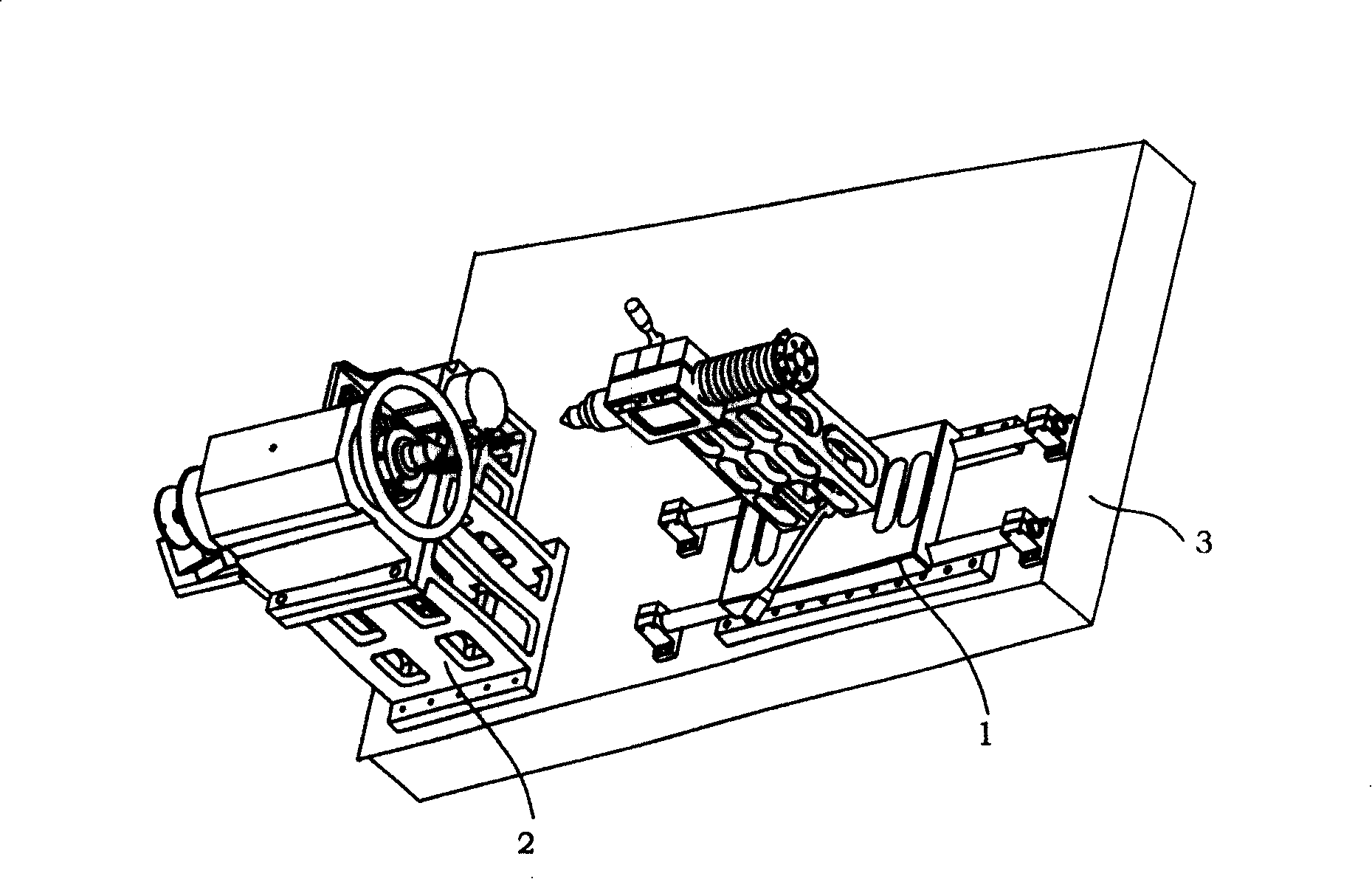
[0030] The present invention is a fiber collection mechanism of an automatic optical fiber winding machine, which is composed of two parts: a fiber collection sliding mechanism 1 and a fiber collection driving mechanism 2, and the fiber collection sliding mechanism 1 and the fiber collection driving mechanism 2 are installed on the automatic fiber optic winding machine on the coaxial line of the worktop 3 (see figure 1 shown); where,

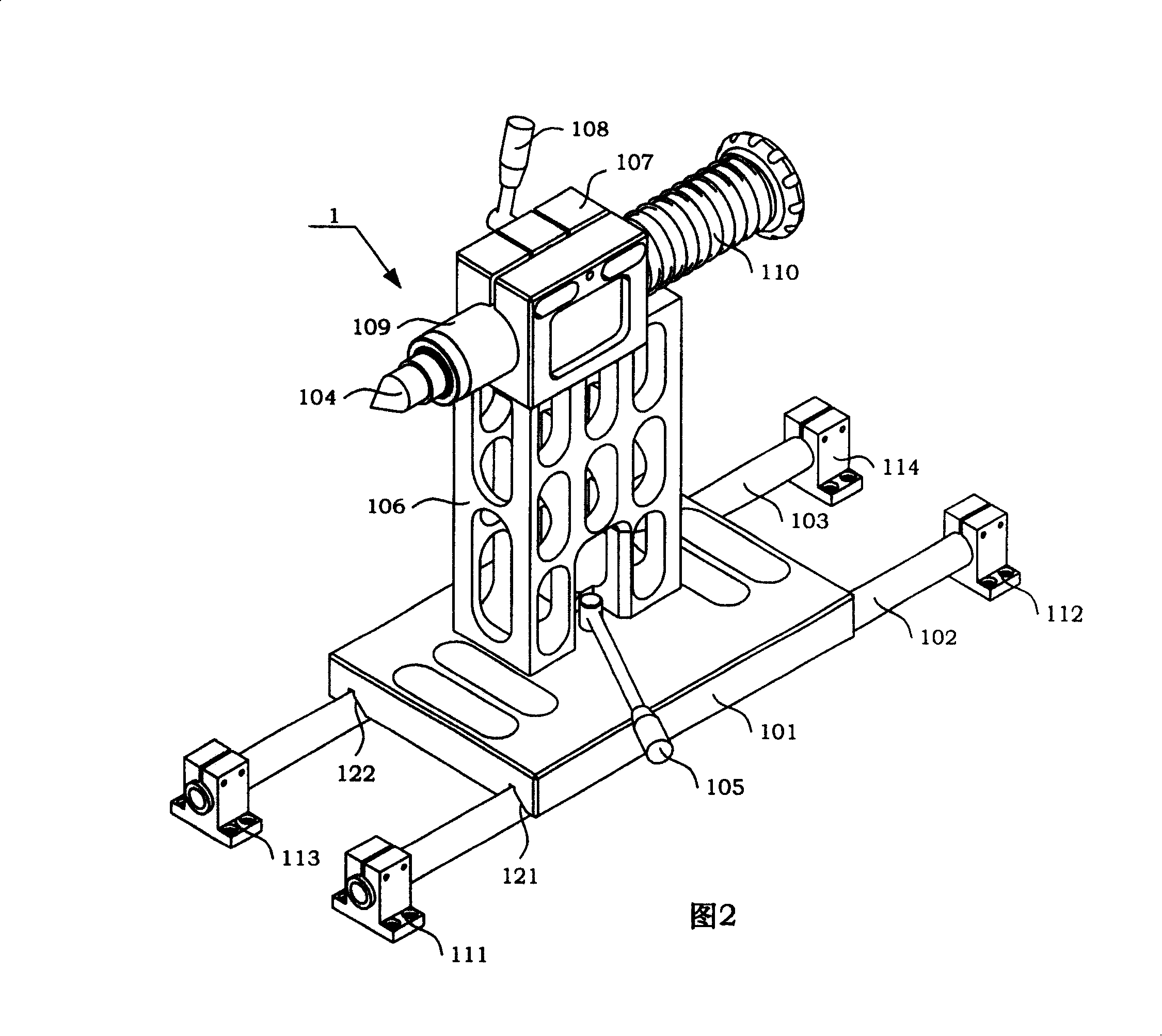
[0031] The two ends of the front slide rail 103 of the fiber collecting sliding mechanism 1 (shown in Fig. 2) are respectively installed on the mounting base C 113 and the mounting base D 114, and the two ends of the rear slide rail 102 are respectively installed on the mounting base A 111 and the mounting base B 112, the positional relationship of the four mounts is: mount A 111 is parallel to mount C 113, mount B 112 is para...


PUM


Abstract

The present invention discloses an automatical optical fiber winder mechanism, which consisting of fiber winder sliding mechanism and driving mechanism that installed on working deck coaxial line of automatical optical fiber circling unit; optical fiber tube two ends respectively fit on top of fiber winder sliding mechanism and driving mechanism, motor driving master gear through synchronizing toothed belt driving engaged wheel, thereby to make principal axes assembly of fiber winder driving mechanism rotation to complete optical fiber winding on optical fiber tube. In said invention, position between driving part and slipper of fiber winder mechanism is adjustable to make uniformly winding.

Description

technical field [0001] The invention relates to a fiber collecting mechanism of an automatic optical fiber looping machine. Background technique [0002] The fiber optic gyroscope was born in 1976. It is a new type of sensor that uses fiber optic sensing technology to measure the space inertial rotation rate. It has developed into a new mainstream instrument with epoch-making characteristics in the field of inertial technology. Compared with the laser gyroscope, it has higher precision, low cost, small size and light weight. The application prospect of fiber optic gyroscope is very broad. It is not only used for aircraft and ship navigation, missile guidance, and high-precision position control of spacecraft, but also can be used for civilian use in the guidance of high-end cars, as well as robots and automatic control systems, etc. . [0003] The fiber optic ring is the sensing core of the fiber optic gyroscope, and its basic requirements are a large extinction ratio and ...

Claims


Application Information

Patent Timeline
Patent Type & Authority Patents(China)
IPC IPC(8): G02B6/00G01C19/72
Inventor 董全林张春熹杜新政孟照魁林恒
Owner BEIHANG UNIV
Why Eureka
Try Eureka