Cooled high intensity gas discharge lamp

A technology of high-pressure gas and discharge lamps, which is applied in the direction of high-pressure discharge lamps, gas discharge lamps, parts of gas discharge lamps, etc., which can solve problems such as difficulties, limitations, and increased lamp power, so as to reduce cooling, increase lamp power, and prevent The effect of mercury condensation

Inactive Publication Date: 2008-07-09
KONINKLIJKE PHILIPS ELECTRONICS NV
View PDF4 Cites 0 Cited by
  • Summary
  • Abstract
  • Description
  • Claims
  • Application Information

AI Technical Summary

Problems solved by technology

However, due to internal convection, the area above the discharge chamber is mainly heated and its thermal conductivity can only be increased to a limited extent by designing the bulb accordingly, so it is difficult to observe this maximum difference and the power increase of the lamp is only limited

Method used


Image

  • Cooled high intensity gas discharge lamp
  • Cooled high intensity gas discharge lamp
  • Cooled high intensity gas discharge lamp

Examples


Embodiment Construction

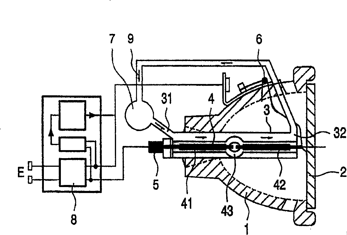
[0033] figure 1 A UHP lamp according to the invention is shown schematically in cross-section in a horizontal installation position. The UHP lamp has a reflector 1 , the opening of which is preferably closed by a front glass 2 . Windshield 2 forms a light exit surface and serves to protect the surroundings in the event of damage to the lamp. Windshield 2 can also be designed as a filter glass for the light generated.

[0034] An electrode arrangement 4 protrudes into the housing 1 from an opening opposite the end of the reflector housing 1 . The electrode arrangement 4 basically comprises a first electrode 41 and a second electrode 42 which are located in a bulb 43 and between opposite tips of the electrodes cause an arc discharge in a discharge chamber 431 of the bulb 43 . The other ends of the electrodes 41, 42 are respectively connected to the electric contacts 5, 6 of the lamp, and the power supply device 8 inputs the feed voltage required for lamp operation through the...


PUM


Abstract

The invention relates to a cooled high intensity gas discharge lamp. Said lamp comprises at least a cooled bulb (43), which hermetically seals a discharge chamber (431) that is filled with a gas, whereby at the moment of discharge, an inhomogeneous temperature distribution is present, at least in the discharge chamber (431) and a cooling device (7) containing a coolant, which produces a directional coolant stream (9). According to the invention, a liquid coolant acts on the bulb (43), the lamp can be operated with an increased performance and the coolant stream (9) is formed in such a way that devitrification of the bulb (43) and condensation of the gas is substantially prevented during increased power consumption.

Description

technical field [0001] The invention relates to a cooled high-pressure gas discharge lamp having at least one cooled bulb which hermetically closes a gas-filled discharge chamber, at least in which an inhomogeneous temperature exists during the gas discharge Distributed, the discharge lamp also includes a cooling device with a coolant that generates a directed flow of the coolant. Background technique [0002] Because of their optical properties, high pressure gas discharge lamps (high intensity discharge (HID) lamps) and especially ultra high performance (UHP) lamps are preferred for projection. [0003] For this application, a light source that is as point-shaped as possible is desired so that the length of the arc formed between the electrode tips does not exceed about 0.5 mm to 2.5 mm. It is also desirable that the light intensity be as high as possible and that the spectral composition of the light be as natural as possible. [0004] These properties are currently bes...

Claims


Application Information

Patent Timeline
Patent Type & Authority Patents(China)
IPC IPC(8): H01J61/52G03B21/14F21S2/00F21S8/12F21V29/00F21V29/02F21Y101/00G03B21/16G03B21/20H01J61/00H01J61/86
CPCH01J61/86H01J61/52
Inventor H·莫恩奇J·A·J·斯托菲斯
Owner KONINKLIJKE PHILIPS ELECTRONICS NV
Why Eureka
Try Eureka