Multifunctonal low temp tester for rubber

A multi-function, tester technology, applied in the direction of testing material hardness, instruments, measuring devices, etc., can solve the problems of high measurement cost, large test error, slow heat conduction, etc., achieve good working conditions, improve test accuracy, and improve work efficiency Effect

A multi-function, tester technology, applied in the direction of testing material hardness, instruments, measuring devices, etc., can solve the problems of high measurement cost, large test error, slow heat conduction, etc., achieve good working conditions, improve test accuracy, and improve work efficiency Effect

CN100405039CInactive Publication Date: 2008-07-23陈彩多

Image

  • Multifunctonal low temp tester for rubber
  • Multifunctonal low temp tester for rubber

Examples


Embodiment Construction

[0023] The present invention will be further described in detail below in conjunction with the accompanying drawings and embodiments.

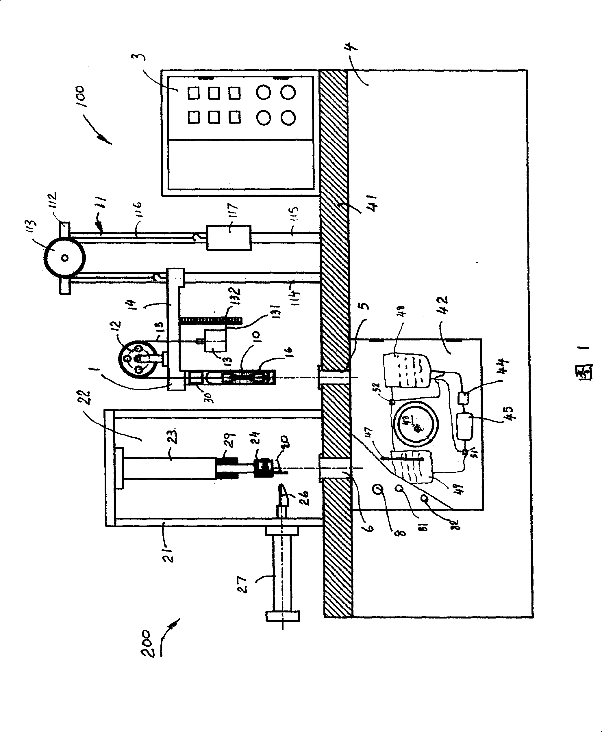
[0024] Fig. 1 shows an embodiment of the multifunctional rubber low temperature tester of the present invention. It includes a low-temperature control box 4 with a working table 41, in which a low-temperature room 42 is set for the vertical sliding direction of the test piece 10; the upper part of the table 41 is respectively provided with a cold resistance coefficient measuring device 100. Low-temperature brittleness testing device 200, electronically controlled display screen 3; on the table 41, a feed well 5, 6 is respectively set for the feeding directions of the cold resistance coefficient testing device 100 and the low-temperature brittleness testing device 200.

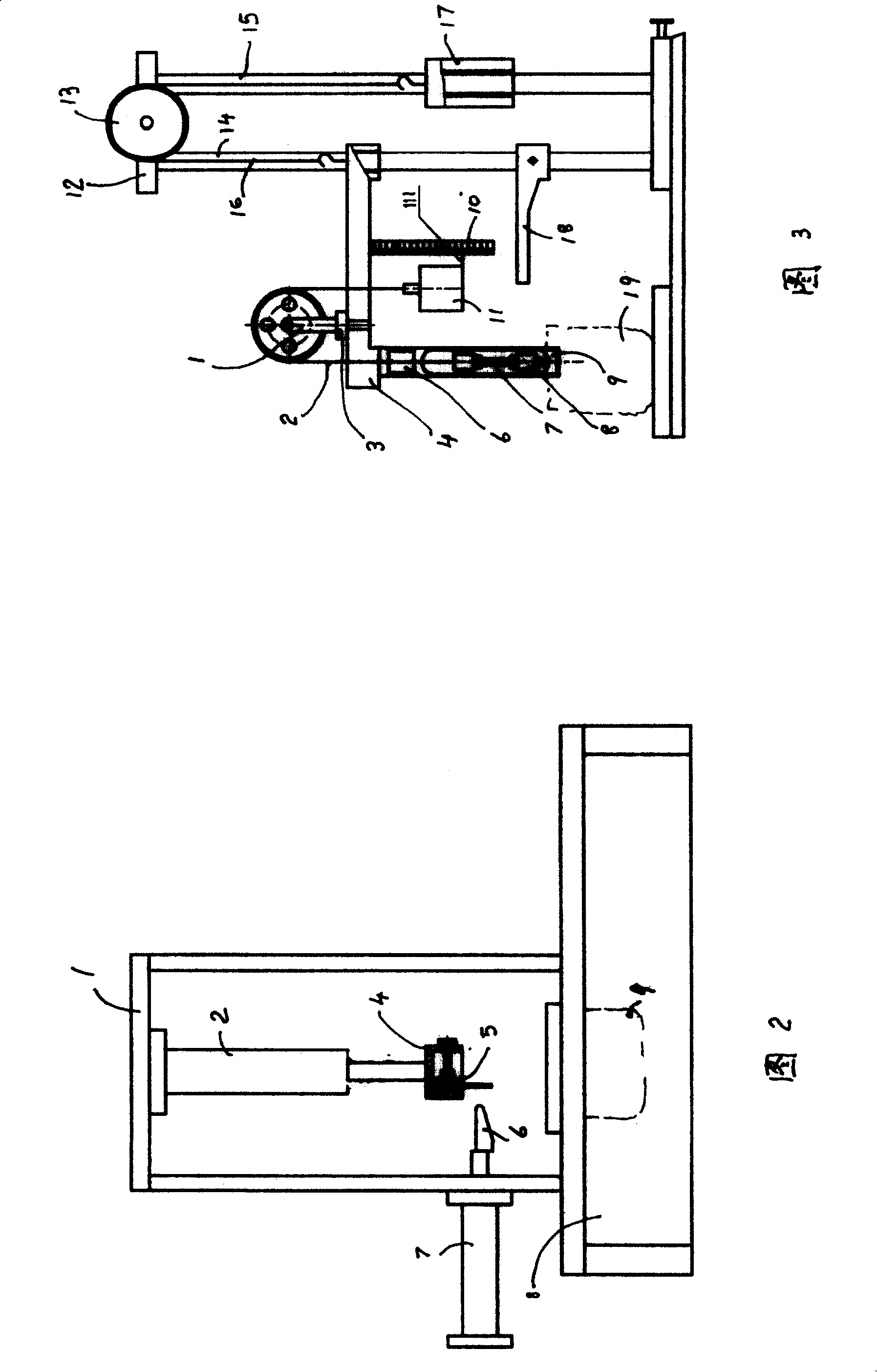
[0025]The cold resistance coefficient measuring device 1 includes a counterweight part 11, and the counterweight part 11 is connected to the right end of the sliding bracket 14...


PUM


Abstract

The test set consists of low temperature thermal container with desktop as well as devices and parts above desk and devices and parts below desk. Devices and parts above desk includes: device for measuring cold tolerant coefficient, device for measuring low temperature brittleness, feeding wells taking in samples for the said two devices, display screen with programmable controller. Devices and parts below desk include: cold chamber including minitype pump and connected radiator. Controlling and testing signals are displayed on screen. The test set provides multiple functions, improves working environment and condition, raises efficiency and precision, lightens labor intensity.

Description

technical field [0001] The invention relates to a rubber testing instrument, in particular to a multi-functional rubber low temperature testing instrument capable of testing the cold resistance coefficient, brittleness, hardness and other indicators of vulcanized rubber products at low temperature at the same time. Background technique [0002] The cold resistance coefficient, brittleness, and hardness of vulcanized rubber products at low temperatures are the main indicators for evaluating rubber products, and they are also key items affecting rubber products. The three standards of GB6035-82 "Determination of Tensile Cold Resistance Coefficient of Vulcanized Rubber" and GB / T531-1999 "Test Method for Indentation Hardness of Rubber Pocket Durometer" all stipulate detailed measurement methods and assessment indicators. [0003] According to the measurement method of GB6035-82 "Determination of Cold Resistance Coefficient of Tensile Rubber of Vulcanized Rubber", the existing co...

Claims


Application Information

Patent Timeline
23 Jul 2008
Publication
CN100405039C
IPC
G01N3/18; G01N3/54; G01N25/12; G01N3/60
Inventors
陈建会; 陈中敢