Eureka AIR delivers breakthrough ideas for toughest innovation challenges, trusted by R&D personnel around the world.

Power amplifier circuit with increased back-off capability and power added efficiency

A technology of power amplifier and carrier amplifier, applied in power amplifier, amplifier with distributed constant in coupling network, amplifier with semiconductor device/discharge tube, etc., can solve problems such as limited improvement

Active Publication Date: 2008-07-30
CREE INC
View PDF1 Cites 0 Cited by
  • Summary
  • Abstract
  • Description
  • Claims
  • Application Information

AI Technical Summary

Problems solved by technology

This technique is clearly applicable when the total output power is very low (below 1 watt), but it provides limited improvement when the output power is in the 10-100 watts CW range

Method used


Image

  • Power amplifier circuit with increased back-off capability and power added efficiency
  • Power amplifier circuit with increased back-off capability and power added efficiency
  • Power amplifier circuit with increased back-off capability and power added efficiency

Examples


Embodiment Construction

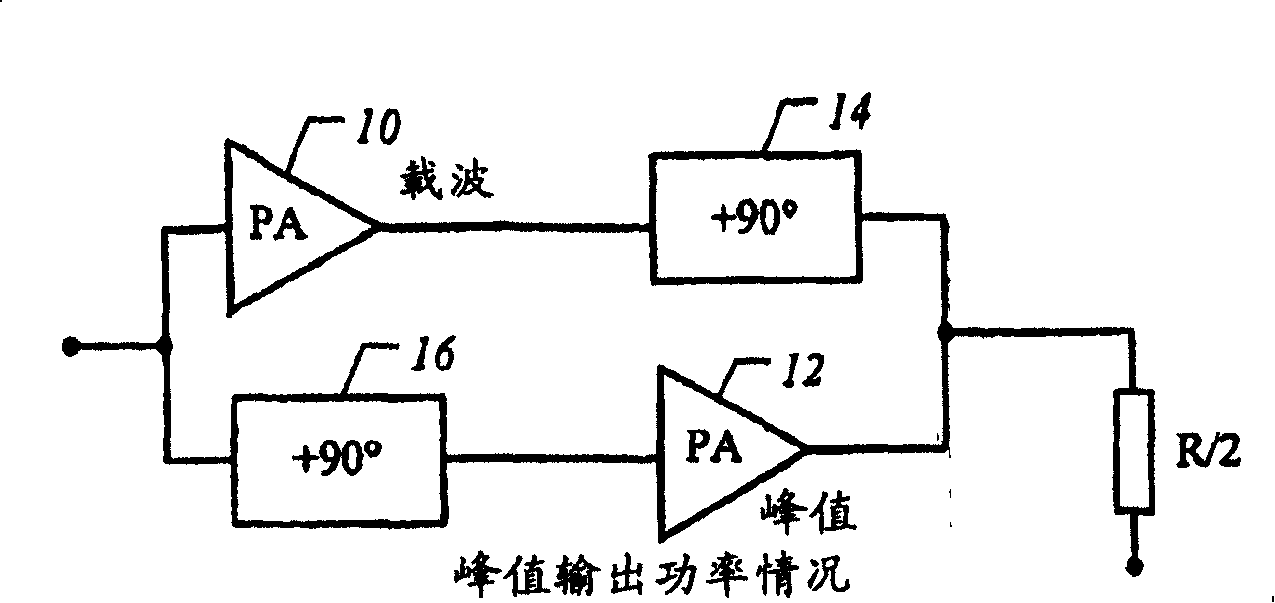
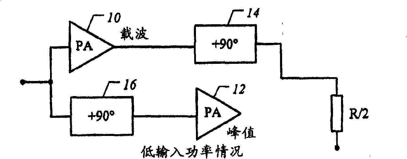
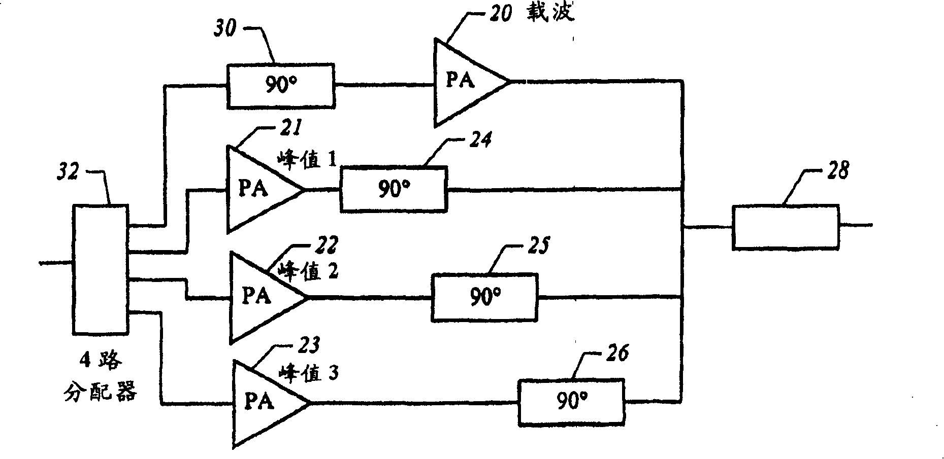
[0023] The present invention can be seen as a modification of the Doherty power amplifier in which one or more peak amplifiers are added and an N-way splitter is provided for the carrier amplifier and the N-1 peak amplifiers. To facilitate the practical construction of the amplifier circuit, the Doherty amplifier quarter-wavelength converters on the input of the peaking amplifier and on the output of the carrier amplifier can be swapped without affecting performance. However, in this case, those skilled in the art will understand that the impedance matching network of the amplifier should be adjusted to account for the repositioning of the quarter wavelength converter. Only a single 90° (quarter wavelength) phase length is required at the carrier amplifier input, making it easier to implement multiple peaking amplifiers with multiple power splitters.

[0024] figure 2 is a functional block diagram of one embodiment of a power amplifier comprising a carrier amplifier 20 and th...


PUM


Abstract

An RF power amplifier circuit for amplifying an RF signal over a broad range of power with improved efficiency includes a carrier amplifier for amplifying an RF signal over a first range of power and with a power saturation level below the maximum of the broad range of power is disclosed. One or more peak amplifiers are connected in parallel with the carrier amplifier with each of the peak amplifiers being biased to sequentially provide an amplified output signal after the carrier amplifier approaches saturation. The input signal is applied through a signal splitter to the carrier amplifier and the plurality of peak amplifiers, and an output for receiving amplified output signals from the carrier amplifier and the plurality of peak amplifiers includes a resistive load R / 2. The split input signal is applied through a 90 DEG transformer to the carrier amplifier, and the outputs of the peak amplifiers are applied through 90 DEG transformers to a output load. When operating below saturation, the carrier amplifier delivers power to a load of 2R when the carrier amplifier delivers current to the load, which is one-half the current at maximum power and the amplifier is saturated. The signal splitter can split the input signal power equally among the carrier and one or more peak amplifiers, or the input signal can be split unequally with the carrier amplifier receiving less input power than each of the peak amplifiers and vice versa.

Description

technical field [0001] The present invention relates generally to RF power amplifier circuits, and more particularly, the present invention relates to RF power amplifier circuits suitable for use in modern wireless communication systems that require a large output power range in base stations employing digital modulation. Background technique [0002] Power amplifiers in base stations often operate at output power levels that are much less than peak power. Unfortunately, compensating the power level reduces the efficiency of the power amplifier in the transmitter. In conventional amplifiers, there is a direct relationship between efficiency and input drive level. Therefore, high efficiency (DC to RF conversion efficiency) is not achieved until the RF input power level becomes sufficient to drive the amplifier into compression or saturation. Since in a multicarrier communication system the amplifier must remain as linear as possible, this high efficiency region cannot be us...

Claims


Application Information

Patent Timeline
Patent Type & Authority Patents(China)
IPC IPC(8): B65D51/16B65D51/24H03F3/68H01LH03F1/02H03F1/07H03F1/32H03F3/24H03F3/60
CPCH03F1/32H03F1/0288H03F3/602H03F2201/3203H03F1/0277H03F2200/451B65D51/16B65D51/24H03F3/60H03F3/68
Inventor R·S·彭格利S·M·伍德
Owner CREE INC
Why Eureka
Eureka Blog
Learn More