Amplifier

一种放大器、多级放大器的技术,应用在放大器、改进放大器以提高效率、改进放大器以减少非线性失真等方向,能够解决不能采用放大级、信号畸变等问题,达到高功率附加效率的效果

Inactive Publication Date: 2007-03-07
NEC CORP
View PDF6 Cites 16 Cited by
  • Summary
  • Abstract
  • Description
  • Claims
  • Application Information

AI Technical Summary

Problems solved by technology

The fifth conventional amplifier has the fifth problem that the injection amount must be adjusted by feedback, feedforward, etc., because the optimal injection amount depends on the input amplitude
[0069] As the third problem mentioned above, in order to increase the efficiency of additional power at low output, the first to third conventional amplifiers have disadvantages in that when they are used with a bias close to the class B state, due to the gain extension while the signal is distorted
[0070] Also, as the fourth problem mentioned above, the fourth conventional amplifier has the disadvantage of not being able to use amplification stages, and due to the third problem mentioned above, all stages exhibit better power added efficiency at low output
[0071] Then, the fifth problem mentioned above, the fifth conventional amplifier also has the disadvantage that due to the dependence of the optimum injection amount on the input amplitude, in differential frequency signal injection, the injection amount must be adjusted by feedback, feedforward, etc.

Method used


Image

  • Amplifier
  • Amplifier
  • Amplifier

Examples


no. 1 example

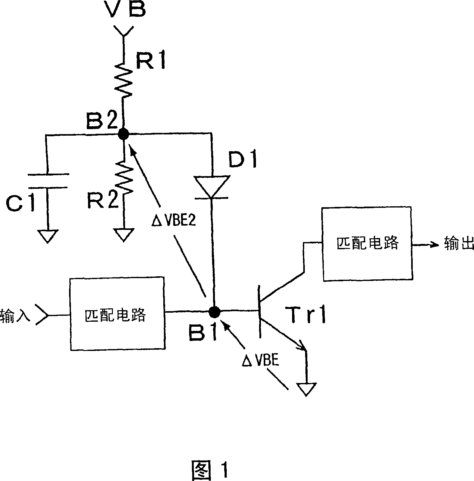
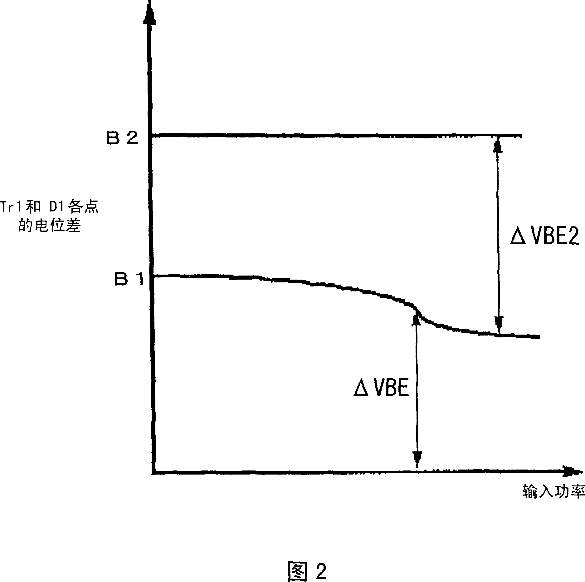
[0146] FIG. 24 is an amplifier diagram illustrating the phase conversion of IM3 with respect to the fundamental wave according to the first embodiment of the present invention. The amplifier transistor 1 constitutes an amplifier circuit whose emitter is grounded, wherein the base of the transistor 1 is connected to an input matching circuit 3 and a cathode of a bias supply diode 4 via an impedance element 2 . The anode of the bias providing diode 4 is connected to a reference power supply 5 which presents a very low impedance at high frequencies. The collector of the transistor 1 is connected to the collector power source 7 through the load 6 and connected to the output terminal 9 through the output matching circuit 8 .

[0147] Fig. 24 illustrating this embodiment corresponds to Fig. 1 illustrating the first conventional example. Comparing the first embodiment illustrated in FIG. 24 with the first conventional example of FIG. 1, in the prior art, the bias supply diode D1 cat...

no. 2 example

[0149] FIG. 27 is a diagram illustrating an amplifier that converts the phase of IM3 with respect to the fundamental wave according to the second embodiment, and corresponds to FIG. 4 of the second conventional example. This embodiment utilizes the base-emitter of bias providing transistor 11 in place of diode 4 in the first embodiment. Therefore, its effects and operations are the same as those of the first embodiment. When the reference power supply 5 is realized by a resistor, the resistor causes a voltage drop, so this embodiment alleviates the second problem mentioned above. In this embodiment, since the bias voltage is also supplied to the amplifying transistor 1 via the impedance element 21, this impedance element 21 does not block any DC current. Since this embodiment is substantially the same in effect and operation as the first embodiment described above, they will be described together below.

[0150] Fig. 25 is a diagram for describing a second embodiment of the ...

no. 3 example

[0158] FIG. 30 is a diagram illustrating an amplifier that converts the phase of IM3 with respect to the fundamental wave according to a third embodiment of the present invention. The amplifier transistor 1 constitutes an amplifier circuit whose emitter is grounded, wherein the base of the transistor 1 is biased by a bias supply diode 23 . Also, the base of the same transistor 1 is connected to the input matching circuit 3 and the bias supply diode 24 through the impedance element 25 . The anodes of the bias supply diodes 23 and 24 are both connected to the reference power supply 5 . The collector of the transistor 1 is connected to the collector power supply 7 through the load 6 and also connected to the output terminal 9 through the output matching circuit 8 .

[0159] Since this embodiment is the same in effect and operation as the sixth embodiment, it will be described together in the sixth embodiment later.


PUM


Abstract

The present invention provides an apparatus for compensating distortion of a multi-stage amplifier having gain extension characteristics. The present invention also provides a method for biasing the amplification stages closer to a Class B regime exhibiting higher power added efficiency at low output, so as to have gain extension characteristics in all stages of a multistage amplifier. The amplifier of the present invention has the characteristic of gain expansion, and it shows that the gain increases with the increase of the input power or output power within a certain range of input power or output power. The amplifier is characterized in that the emitter-grounded amplifier circuit comprising a first bipolar transistor has a base terminal which passes through a first impedance element which does not block direct current and an input matching circuit and a first diode which provides a bias voltage. The cathode is connected, while the first diode has an anode connected to a reference power supply that presents a very low impedance at high frequencies.

Description

technical field [0001] The present invention relates to an amplifier, and more particularly to an amplifier used in radio communication for controlling output power over a wide range, which amplifies input power by a plurality of transistors connected in a multi-stage manner to generate amplified power . Background technique [0002] Power amplifiers using bipolar transistors with grounded emitters integrally require a base bias circuit that operates close to a regulated power supply. A regulated power supply is more suitable for biasing circuits than a rectified current source for reasons explained below. [0003] Consider the case of a radio frequency (RF) input applied to a grounded emitter bipolar transistor whose base is provided with a bias from a regulated power supply. This grounded-emitter bipolar transistor exhibits small-signal operation when the input power is small enough that its collector current is substantially equal to the so-called bias current flowing t...

Claims


Application Information

Patent Timeline
Patent Type & Authority Applications(China)
IPC IPC(8): H03F1/32H03F1/02H03F1/30H03F3/343
CPCH03F3/343H03F1/302H03F1/0266H03F1/3276
Inventor 青木雄一
Owner NEC CORP
Why Eureka
Try Eureka