Radio frequency power amplifier supporting multi-mode and multi-frequency, chip and communication terminal

A radio frequency power, multi-mode and multi-frequency technology, applied to amplifiers, amplifiers with semiconductor devices/discharge tubes, electrical components, etc., can solve the problem that class E power amplifiers cannot be used on a large scale, and achieve both output power and power Additional efficiency and loss reduction effects

Active Publication Date: 2017-05-10
VANCHIP TIANJIN TECH
View PDF8 Cites 17 Cited by
  • Summary
  • Abstract
  • Description
  • Claims
  • Application Information

AI Technical Summary

Problems solved by technology

However, Class E power amplifiers have very significant design constraints
These factors include transistor parasitic capacitance, matching network, bias circuit, switch duty cycle, etc., which together lead to the inability of large-scale application of Class E power amplifiers in the field of civil communication.

Method used


Image

  • Radio frequency power amplifier supporting multi-mode and multi-frequency, chip and communication terminal
  • Radio frequency power amplifier supporting multi-mode and multi-frequency, chip and communication terminal
  • Radio frequency power amplifier supporting multi-mode and multi-frequency, chip and communication terminal

Examples


Embodiment Construction

[0030] The technical content of the present invention will be further described in detail below with reference to the drawings and specific embodiments.

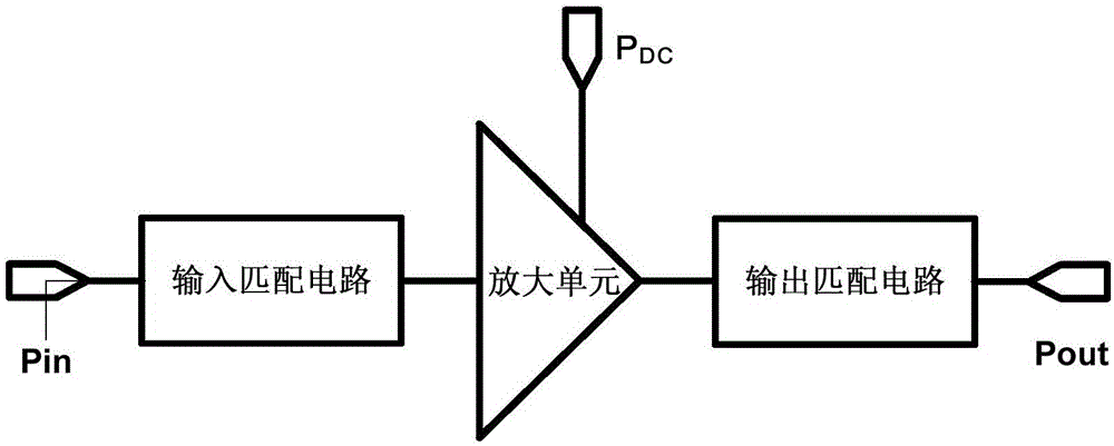
[0031] In order to fully explain the conditions and principles of further improving the power added efficiency under the premise of maximizing the output power, the structure of the radio frequency power amplifier is first defined in the present invention. figure 1 Is a simplified schematic diagram of the RF power amplifier, where P in Is the input power, P out Is the output power, P DC Is the DC power consumption of the power amplifier. The time domain expressions of the voltage and current of a working RF power amplifier are as follows:

[0032]

[0033]

[0034] In the above formula, ξ n with Represents the phase of the current and voltage of the nth harmonic. The impedance of the nth harmonic can be expressed as:

[0035]

[0036]

[0037] DC power consumption of the circuit P DC And the power consumed by the circuit itsel...


PUM


Abstract

The invention discloses a radio frequency power amplifier supporting multi-mode and multi-frequency, a chip and a communication terminal. The radio frequency power amplifier comprises a control and bias unit and at least two amplified emission paths, and the control and bias unit is separately connected with the amplified emission paths; and the control and bias unit controls the corresponding amplified emission path to locate in a turn-on state according to the frequency band of inputting a radio frequency signal and locating the rest amplified emission paths in a closed state. According to the radio frequency power amplifier disclosed by the invention, the optimal amplified emission path can be selected according to different frequency bands, the turn-on and turn-off of a corresponding amplification unit and a switching unit are controlled by the control and bias unit so as to amplify the radio frequency signals of different frequency bands, on one hand, the design principle of the F type power amplifiers is satisfied as much as possible to consider both of the output power and the power additional efficiency, on the other hand, corresponding harmonic waves of the amplified emission paths are filtered, so the demands of the carrier aggregation technology can be met, and the loss of the radio frequency signals on the output paths is reduced.

Description

Technical field [0001] The present invention relates to a radio frequency power amplifier, in particular to a radio frequency power amplifier supporting multi-mode and multi-frequency, and also to a chip and a communication terminal including the radio frequency power amplifier, belonging to the technical field of radio frequency integrated circuits. Background technique [0002] As we all know, radio frequency power amplifiers are widely used in the field of wireless communications. In order to adapt to the increasingly higher requirements of modern communication business for communication speed, various communication terminal equipment must gradually improve their technical indicators to meet this demand. For example, in order to meet the data transmission rate requirements of 4G mobile phones, mainstream manufacturers such as Qualcomm, MediaTek and Spreadtrum have begun to adopt Carrier Aggregation (CA) in their products. Correspondingly, the RF power amplifier also needs to ...

Claims


Application Information

Patent Timeline
Patent Type & Authority Applications(China)
IPC IPC(8): H03F3/217H03F3/213
CPCH03F3/213H03F3/217Y02D30/70
Inventor 牛旭白云芳
Owner VANCHIP TIANJIN TECH
Why Eureka
Try Eureka