Multi-mode power amplifier with high efficiency under backoff operation

a power amplifier and backoff operation technology, applied in the direction of amplifier combinations, gated amplifiers, gain control, etc., can solve the problems of high cost, large loss of switches, and non-optimal current consumption, so as to prevent any power leakage, reduce power consumption, and reduce power consumption

Active Publication Date: 2008-02-07
SEMICON COMPONENTS IND LLC
View PDF4 Cites 16 Cited by
  • Summary
  • Abstract
  • Description
  • Claims
  • Application Information

AI Technical Summary

Benefits of technology

[0021] In an embodiment, the multi-mode RF power amplifier assumes at least two operating modes, the first being the HP (higher power) output mode and the second mode being the LP (lower power) output mode. In the HP mode power travels through both paths as described above. In the LP mode, the RF switch is turned off so power travels only through the bypass impedance matching network. In the HP mode, the RF switch is turned on which presents a short circuit with negligible loss, and the input impedance of the first and the bypass impedance matching circuits are about equal, so that power delivered from the first power amplifier is about equally delivered to both the first and bypass impedance matching circuits. However, in other illustrative embodiments, the power delivered to the bypass circuit is larger than that delivered through the RF switch. The result is that substantial power travels through both paths and both contribute to the final HP output.
[0022] Since the power delivered in the HP mode is shared between the two paths, it becomes unnecessary to minimize any power leakage to the bypass impedance matching circuit as described in Kim. The advantages of this operation are: in the LP mode, that the RF switch is turned off to prevent any power leakage to the auxiliary amplifier; increased isolation between the first and the second paths, and this increased isolation allows optimally chosen impedance for the bypass impedance matching network in the second (LP) path presented to the output of the main amplifier. These advantages allow the multi-mode RF power amplifiers to operate with higher efficiency and / or higher output power capability in LP mode operation.

Problems solved by technology

The power added efficiency (PAE, a metric known in the art) of the power amplifiers usually drops off rapidly at backoff or LP (“Low Power” and “back off” are synonymous) levels, resulting in non-optimal current consumption coupled with excessive linearity margin.
As known to those skilled in the art, the excessive linearity margin can be a trade-off for lower current consumption in the design of power amplifiers.
However, any such switches are lossy, costly, several must be used to provide bypassing, and complex control may be required.
Increased power loss and current consumption and large physical size all limit the applications of such circuits in handset power amplifiers.
For example, Kim's five impedance matching circuits are complex and several simultaneous matching requirements under HP and LP modes would require tradeoffs in performances.
If the matching networks are optimized for the best ZintL under LP mode operation, it might not be optimal under HP mode operation which would increase undesired leakage power through Ztrans and degrade HP mode performance.
On the other hand, if the matching networks are optimized for the best ZintL under HP mode operation, then ZintL might not be optimal under LP mode operation which could increase the current consumption of the driver stage.
However, the PA will start to turn on when there is a significant RF power level presented at the PA's input.
This limits the maximum linear output power capability under LP mode operation.
In addition, the impedance presented by the Ztrans matching network to the 1st Z matching network cannot be selected optimally to maximize LP mode efficiency as a result of limited isolation between the two passive matching networks, 2nd Z matching and Ztrans.
The prior art, generally, remains power inefficient due to potential tradeoffs required for matching impedances for HP and LP modes, and the prior art also employs complex circuitry.

Method used


Image

  • Multi-mode power amplifier with high efficiency under backoff operation
  • Multi-mode power amplifier with high efficiency under backoff operation
  • Multi-mode power amplifier with high efficiency under backoff operation

Examples


Embodiment Construction

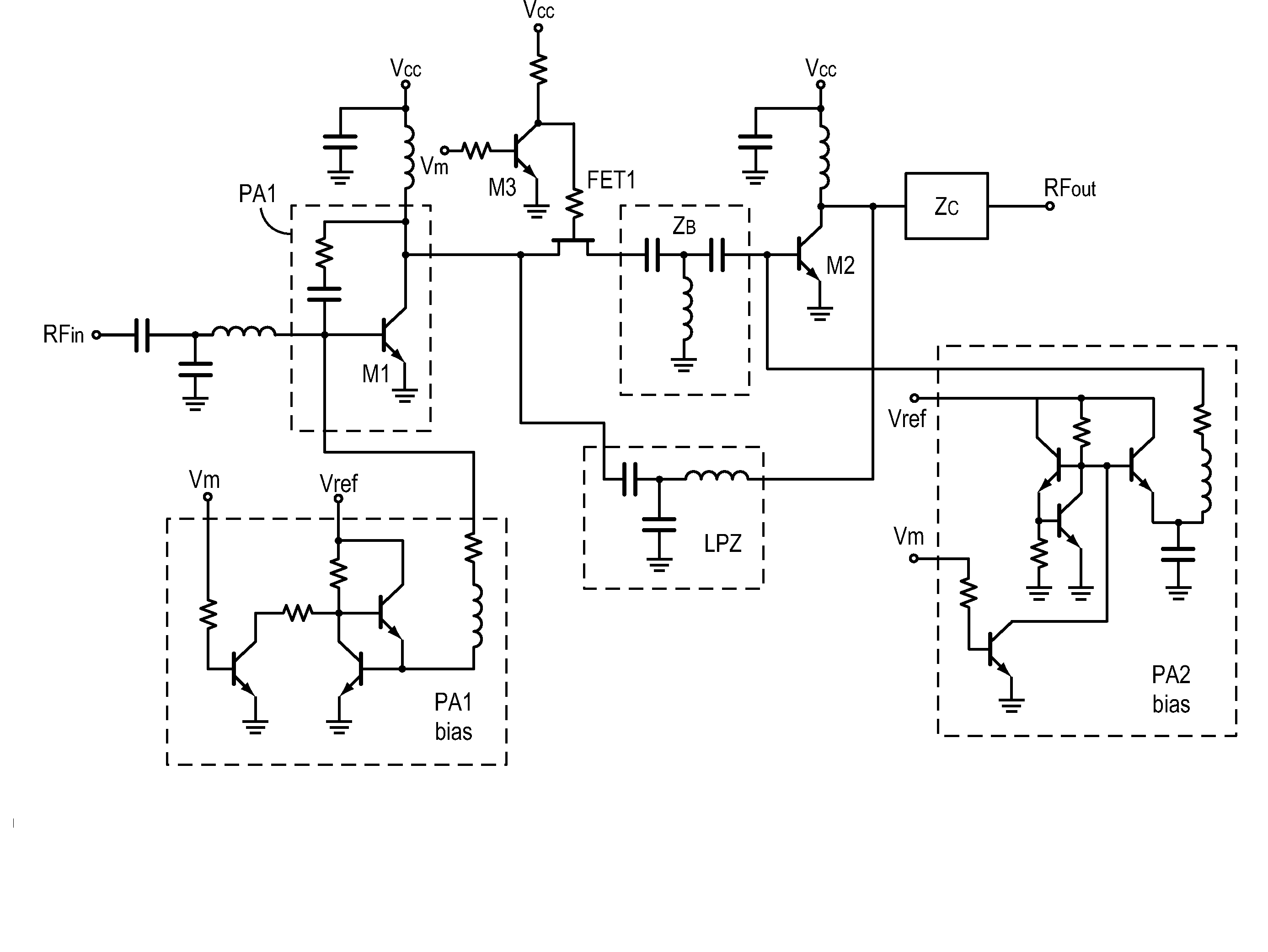
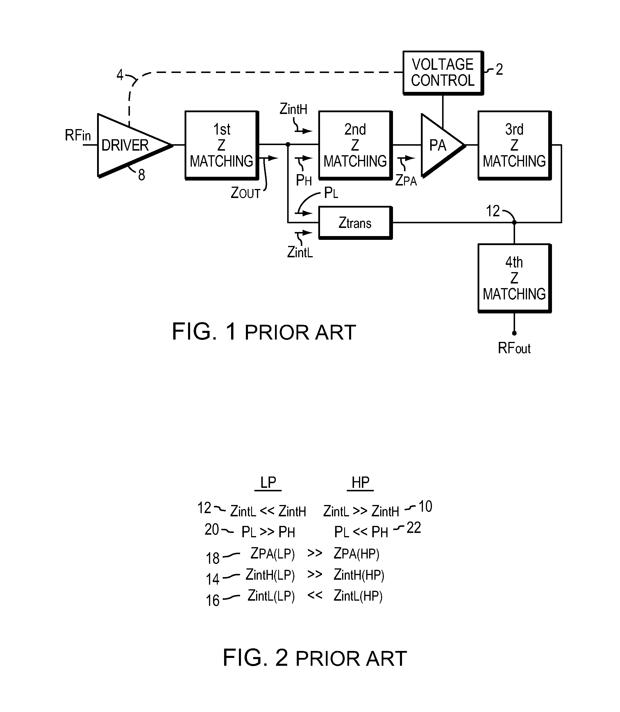
[0040]FIG. 5 illustrates a block diagram circuit incorporating an embodiment of the pre-sent invention. Comparing FIG. 5 with FIG. 1, two impedance matching circuits, the 1st and the 3rd in FIG. 1 are eliminated in FIG. 5. In FIG. 5 there are two power paths, the first being from the input matching network 32 to a first multi-stage power amplifier 33, an RF switch 34, an inter-stage impedance matching network ZB 36, and a multi-stage auxiliary PA (power amplifier) 37 to an output impedance matching network Zc 38. The second path is from the input matching network 32 to the multi-stage power amplifier 33, a LPZ matching network 39 to the output impedance matching network Zc 38.

[0041]“First path” describes the path through the RF switch 34 in the HP mode, while the “second path” describes the path through the LPZ matching network 39. This second path is always operational. These designations are used to prevent confusion with HP and LP modes.

[0042] The bias control 30 in response to...


PUM


Abstract

A multi-mode RF amplifier is disclosed having high and low output power modes and two power paths. A first RF amplifier delivers power to both paths. When the multi-mode RF amplifier is biased into the high power, HP, mode, substantial power is delivered via both (first and second) paths. While in the low power, LP, mode, an RF switch is turned off, creating a high input impedance, open circuit for the first path, and effectively isolating the two paths. Therefore, power is delivered by the first RF amplifier to the second path only. The impedance presented to the output of the first RF amplifier is equal to the input impedance of the second path which may be optimally set for maximizing power added efficiency or output power in LP mode. Note that, in a preferred embodiment, even in the HP mode more power is delivered to the second power path than to the first power path.

Description

CROSS REFERENCE TO RELATED PATENTS [0001] The present application is related to the commonly owned U.S. patent applications: a) Ser. No. 11 / 350,220, filed Feb. 8, 2006, and entitled: “Power Amplifier with Close-Loop Adaptive Voltage Supply,” by G. Hau et al.; and is a continuation-in-part of b) Ser. No. 11 / 385,948, filed Mar. 21, 2006, and entitled “Multi-Mode Power Amplifier with Reduced Low Power Current Consumption,” by G. Hau. [0002] The above applications are hereby incorporated herein by reference.BACKGROUND OF THE INVENTION [0003] 1. Field of the Invention [0004] The present invention relates to power amplifiers and, more particularly, to power amplifiers used in battery powered mobile handsets, and even more particularly to optimizing battery current use in such power amplifiers over a range of output power levels. [0005] 2. Background Information [0006] Radio-frequency (RF) signals generated at a mobile handset generally are amplified, transmitted through the handset antenn...

Claims


Application Information

Patent Timeline
Patent Type & Authority Applications(United States)
IPC IPC(8): H03G3/30H04B1/034
CPCH03F1/0261H03F1/0277H03F1/56H03F3/19H03F3/211H03F3/245H03F2203/7239H03F2200/318H03F2200/411H03F2200/451H03F2203/7206H03F2203/7231H03F2203/7233H03F3/72
Inventor HAU, GARYHUSSAIN, ABID
Owner SEMICON COMPONENTS IND LLC
Why Eureka
Try Eureka