

Power supply for AC elevator
A technology for power supply devices and elevators, which is applied in battery circuit devices, circuit devices, and output power conversion devices, etc., can solve problems such as being difficult to implement, difficult to design rectifier circuits or batteries, etc.
- Summary
- Abstract
- Description
- Claims
- Application Information
AI Technical Summary
Problems solved by technology
Method used
Image

Examples
no. 1 Embodiment
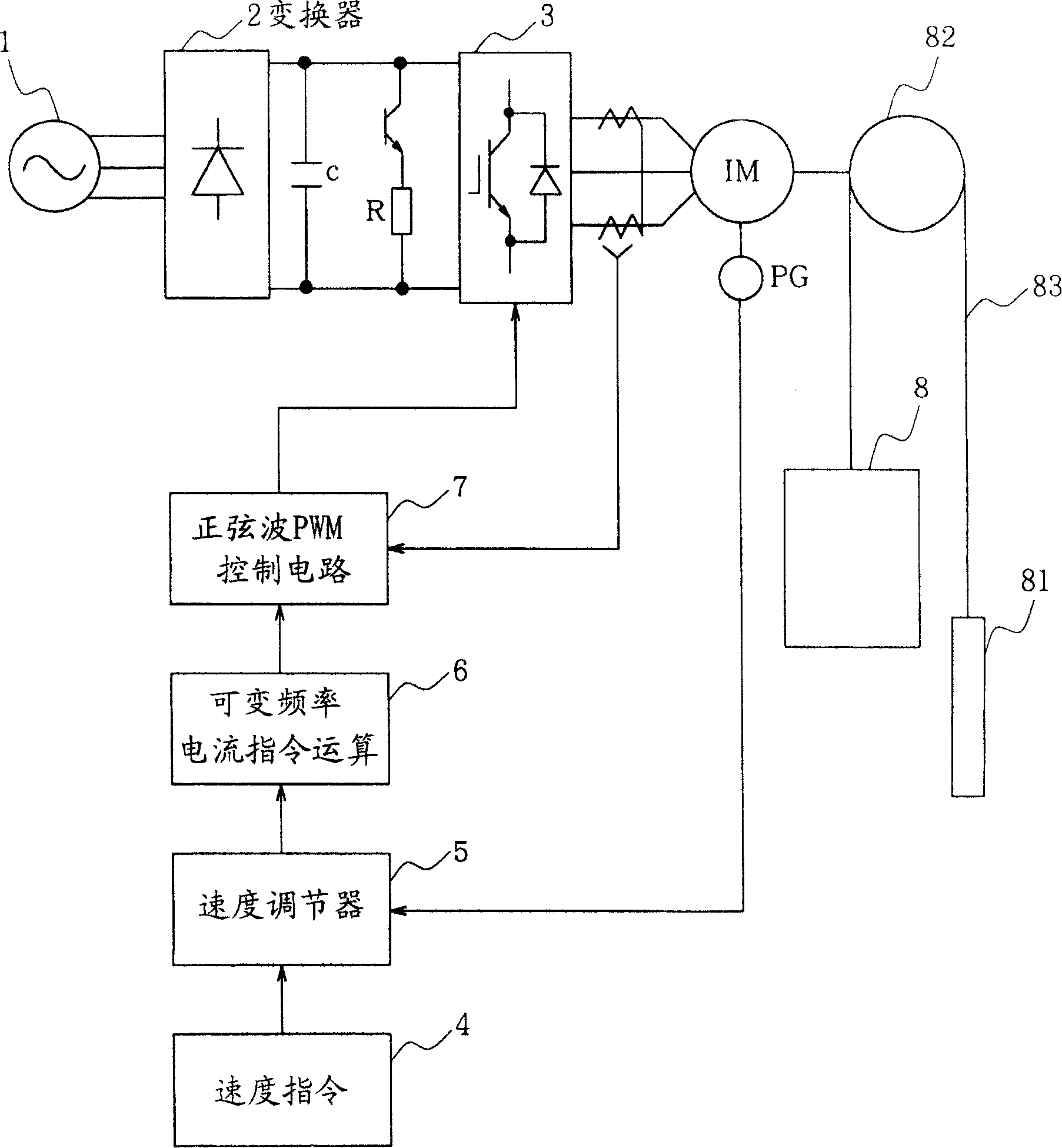
[0038] in such as figure 2 The hoisting device 82 driven by the induction motor IM shown is wound with a cable 83, and one end of the cable 83 is connected to the elevator cage 8, and at the same time, the other end of the cable 83 is connected to the balance weight 81.
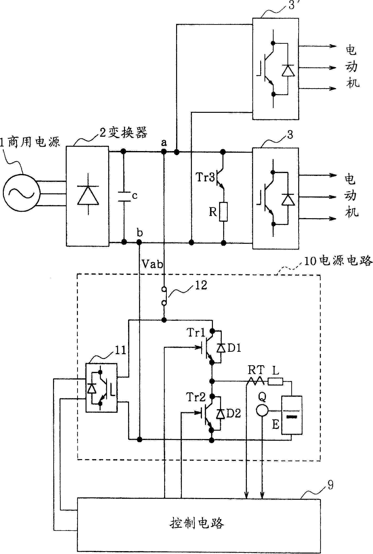
[0039] AC power supplied from commercial power supply 1 is converted into DC power by converter 2 and then input to inverter 3 for conversion into AC power, and the AC current output from inverter 3 is supplied to induction motor IM.
[0040] Inverter 3 consists of figure 2 shown in the well-known PWM control circuit control. That is, in the induction motor IM, a pulse generator PG for detecting the actual speed of the elevator cage 8 is installed, and the speed command 4 for the elevator cage 8 and the output signal of the pulse generator PG are supplied to the speed regulator 5 to generate a speed deviation signal. This speed deviation signal is supplied to a variable frequency current command computin...
no. 2 Embodiment
[0069]This embodiment has the same structure as the first embodiment as a basic structure, and also has a structure for resetting or presetting the capacity gauge by maintaining the battery pack in a charged or discharged state under predetermined conditions.
[0070] That is, in the control system shown in FIG. 4, in the state where the charging prohibition switch S3 is set to off, every predetermined time, for example, 1 hour, from setting the charging and discharging permitting switch S2 to on, to Set the discharge prohibition switch S1 to the off state, switch to set the charge and discharge permit switch S2 to off, set the discharge prohibition switch S1 to the on state, and set the limit value of the discharge side to 0 , to maintain the battery pack E in a charging state (charging mode). The charging mode can also be set while the elevator is stopped.
[0071] As a result, the battery pack E is fully charged until the terminal voltage of the battery pack E becomes suff...
no. 3 Embodiment
[0077] The present invention has the same structure as the first embodiment as a basic structure, and also has the ability to eliminate the charge amount of each single cell constituting the battery pack by boldly maintaining the battery pack in a charged or discharged state under predetermined conditions. Discrete structure.
[0078] In this embodiment, a battery pack E is composed of a plurality of units composed of eight single cells B shown in FIG. An A / D converter 32 for converting the output signal of the amplifier into a digital signal; a microcomputer 33 for turning on / off the switches S1 to S3 shown in FIG. 4 according to the voltage values V1 to Vn obtained from the A / D converter 32 . The microcomputer 33 monitors the voltage values V1~Vn, and when a dispersion (for example, about 0.4V) exceeding the threshold occurs on these voltage values (for example, about 9.6V), the charging and discharging permission switch S2 shown in FIG. 4 is turned on, and the discha...
PUM
 Abstract
Description
Claims
Application Information