Integrated switch power and working method thereof
An integrated switch and power supply technology, applied in the direction of circuits, inductors, electrical components, etc., can solve the problems of large number of components, difficulty in comprehensively realizing the realization index, and difficulty in further improving power conversion efficiency, so as to achieve the effect of improving conversion efficiency
- Summary
- Abstract
- Description
- Claims
- Application Information
AI Technical Summary
Problems solved by technology
Method used
Image
Examples
Embodiment 1
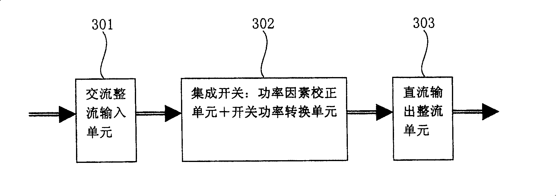
[0063] Such as image 3 As shown, an integrated switching power supply in this embodiment includes: an AC rectification input unit 301 for converting the AC power into a unipolar DC power; a DC output rectification unit 303 for outputting the DC power after rectification;
[0064] It also includes a conversion switch unit 302 for converting the unipolar direct current into a stable high-voltage direct current, and isolating the high-voltage direct current to the direct-current output stage.
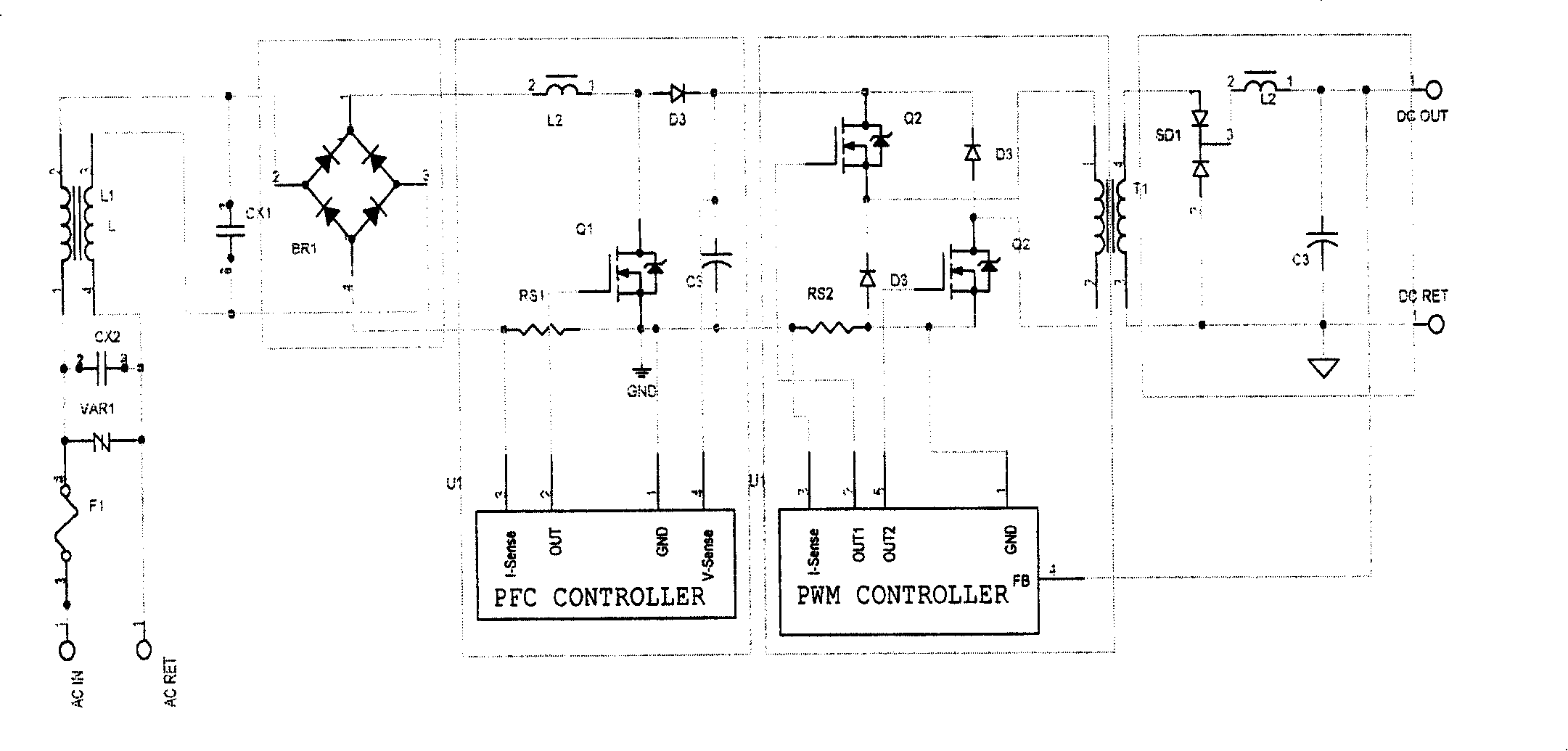
[0065] Such as Figure 5 and Figure 6 It is the schematic diagram of the half-bridge topology of the transfer switch unit, Figure 7 It is the circuit diagram of this embodiment. Wherein the conversion switch unit 302 includes: an energy storage inductor Lpfc, a conversion transformer T1, a capacitor C, a resistor Rsns, a first diode CD1, a second diode D1, a first switch tube PFC1 and a second switch tube SW1 ;
[0066] The transfer switch unit is driven by direct current;
[0067...
Embodiment 2
[0074] Such as Figure 4 As shown, this embodiment provides an integrated switching power supply, including a DC output rectification unit 402 for outputting the DC power after rectification, and a conversion switch unit 401 for converting the AC power into a unipolar DC power, and converting the unipolar The direct current is transformed into a stable high voltage direct current, and the high voltage direct current is isolated and delivered to the direct current output stage.
[0075] Such as Figure 8 , Figure 9 , Figure 10 Shown is the schematic diagram of the full-bridge topology of this embodiment. Such as Figure 13 Shown is the working circuit diagram of the full bridge topology of this embodiment.
[0076] Wherein, the switch unit 401 includes: an energy storage inductor Lpfc, a first transducing transformer T1, a second transducing transformer T2, a capacitor C, a first controllable switching device PFC1, a second controllable switching device PFC2, The third ...
Embodiment 3
[0086] This embodiment provides a working method of an integrated switching power supply, such as image 3 As shown, the integrated switching power supply includes: AC rectification input unit 301, DC output rectification unit 303, transfer switch unit 302;
[0087] The AC rectification input unit 301 converts AC power into unipolar DC power;
[0088] The first controllable switch device, the first unidirectional electronic device, a capacitor and a resistor are connected in series, and the energy storage inductance is connected to the connection point between the first controllable switch device and the first unidirectional electronic device to form A step-up switching circuit, which converts unipolar direct current into high-voltage direct current;
[0089] The transformer, the first controllable switch device, the second controllable switch device, the first unidirectional electronic device, and the second unidirectional electronic device form a forward switching circuit, ...
PUM
 Abstract
Description
Claims
Application Information
 - R&D
- Intellectual Property
- Life Sciences
- Materials
- Tech Scout
- Unparalleled Data Quality
- Higher Quality Content
- 60% Fewer Hallucinations
Browse by: Latest US Patents, China's latest patents, Technical Efficacy Thesaurus, Application Domain, Technology Topic, Popular Technical Reports.
© 2025 PatSnap. All rights reserved.Legal|Privacy policy|Modern Slavery Act Transparency Statement|Sitemap|About US| Contact US: help@patsnap.com


