
Back-light module

A technology for backlight modules and fluorescent tubes, applied in optics, nonlinear optics, instruments, etc., can solve the problems of increasing the cost of inverters, increasing operating voltage and starting voltage, and breakdown of the glass tube wall of fluorescent tubes, and improving efficiency. , Solve the effect of easy deformation, reducing the working voltage and starting voltage

Inactive Publication Date: 2008-08-13
AU OPTRONICS CORP
View PDF4 Cites 0 Cited by
  • Summary
  • Abstract
  • Description
  • Claims
  • Application Information

AI Technical Summary

Problems solved by technology

[0008] However, whether it is a cold cathode fluorescent tube or an external electrode fluorescent tube, when it is used in a large-sized backlight module, it will face a common difficulty, that is, when the length of the tube increases, the required The working voltage and starting voltage of the inverter will also be greatly increased. In this way, in order to provide sufficient working voltage and starting voltage, the cost of the inverter will be greatly increased, and it is more likely that the applied voltage will be too high. As a result, the glass tube wall of the fluorescent tube (especially the external electrode fluorescent tube) is broken down at its electrode.

Method used


Image

  • Back-light module
  • Back-light module
  • Back-light module

Examples


Embodiment Construction

[0050] In order to further reveal the advantages and spirit of the present invention, a detailed description will be made as follows in conjunction with the drawings.

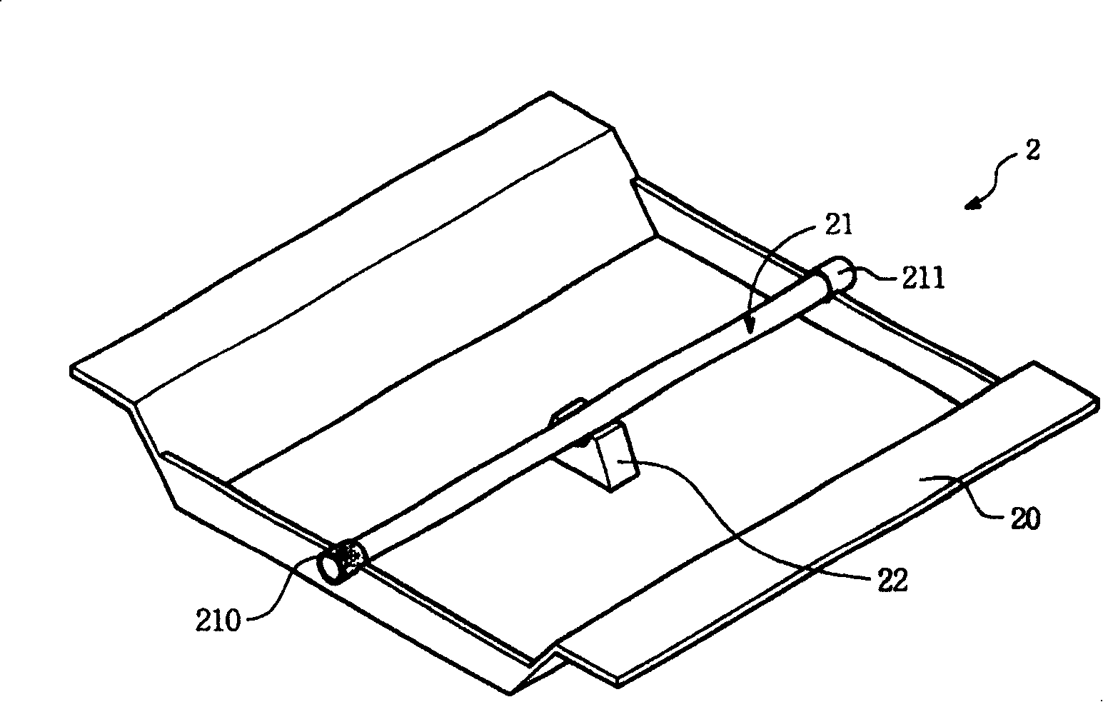
[0051] See Figure 1A , Which is a three-dimensional schematic diagram of the first embodiment of the backlight module disclosed in the present invention.

[0052] The backlight module 2 includes a bottom case 20, a fluorescent tube 21 and a lower bracket 22.

[0053] The fluorescent tube 21, in this embodiment, is an external electrode fluorescent tube, both ends are fixed on the bottom shell, and the outer surface of which is provided with a first electrode 210 and a second electrode 211, which are external electrodes. The first electrode 210 and the second electrode 211 are respectively located at two ends of the fluorescent tube 21.

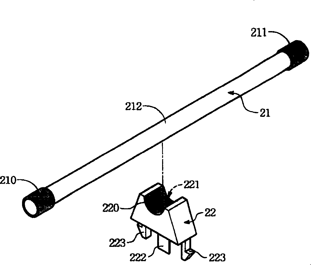
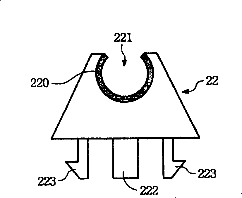
[0054] The lower bracket 22 is fixed on the bottom shell 20. In order to better understand the structure of the lower bracket 22, please refer to it together Figure 1B , Which is ...


PUM


Abstract

The present invention provides a backlight module. It contains one bottom case, one fluorescent tube and one subframe, wherein said fluorescent tube fixed on said bottom case, subframe fixed on bottom case and supporting said fluorescent tube, said subframe surface having one electrode layer directly connecting to said fluorescent tube outer tube wall, thereof dividing fluorescent tube into plurality of different sections, in turn driving, thereby capable of reducing fluorescent tube required operating voltage and starting up voltage.

Description

Technical field [0001] The invention relates to a backlight module, in particular to a backlight module using a lower bracket as a lamp tube electrode. Background technique [0002] Among various image display devices, liquid crystal displays have been widely used in various devices due to their advantages of light weight, small size, low power consumption, and no radiation. [0003] Among them, the liquid crystal display can be divided into two parts, one is the backlight module, which can provide stable and uniform light; the other is the liquid crystal panel (mainly composed of two substrates sandwiching a liquid crystal layer), which is located at the light exit of the backlight module , By controlling the rotation of the liquid crystal molecules in the liquid crystal panel to change the direction of light travel in the liquid crystal panel, resulting in the difference of brightness in different areas of the liquid crystal panel, and achieving the purpose of image display. ...

Claims


Application Information

Patent Timeline
Patent Type & Authority Patents(China)
IPC IPC(8): G02F1/1335
Inventor 蔡宜轩
Owner AU OPTRONICS CORP
Learn More