Cemented oil tank and its producing method

A manufacturing method and technology for fuel tanks, which are applied to the substructure and other directions, can solve the problems of high investment cost of laser welding equipment, unsatisfactory welding quality of fuel tanks, and poor welding effect of dissimilar materials, so as to improve operation safety and reduce dependence. performance and reduce maintenance costs

Active Publication Date: 2008-08-20
METAL INDS RES & DEV CENT
View PDF8 Cites 0 Cited by
  • Summary
  • Abstract
  • Description
  • Claims
  • Application Information

AI Technical Summary

Problems solved by technology

[0009] In addition, although the laser welding method has high precision and higher overall production than the above-mentioned welding methods, the investment cost of laser welding equipment is expensive, and the maintenance cost is relatively high, unless it is used in high-profit and large-volume commercial Products, otherwise it is rare to invest in laser welding

Method used


Image

  • Cemented oil tank and its producing method
  • Cemented oil tank and its producing method
  • Cemented oil tank and its producing method

Examples


Example Embodiment

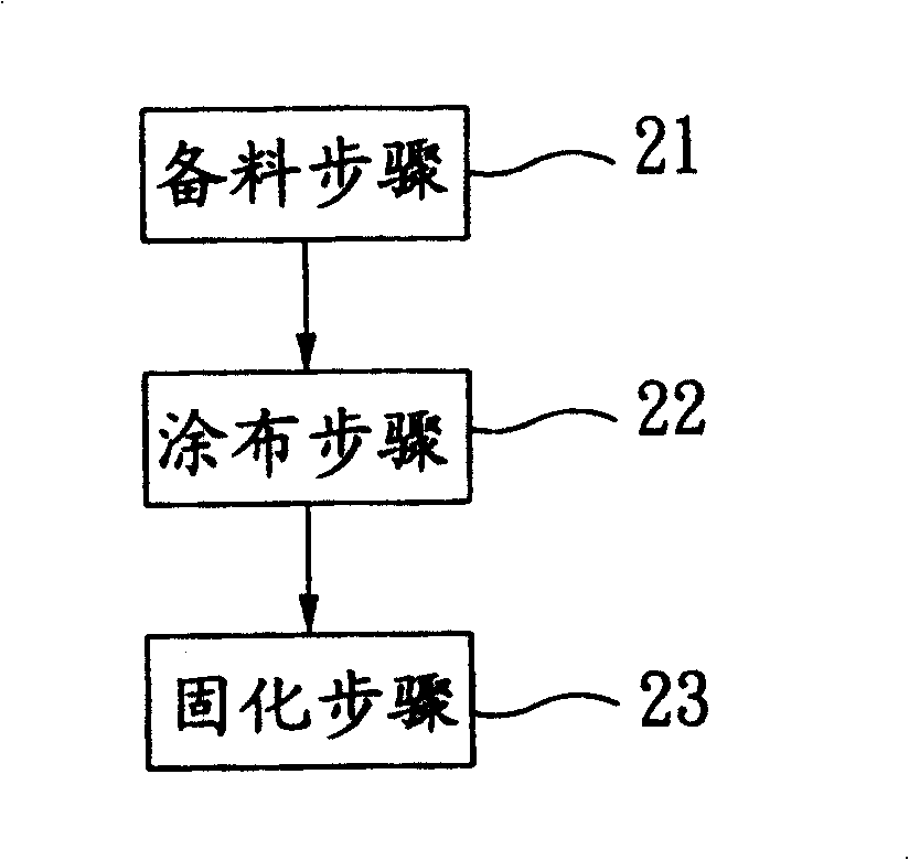
[0039] Such as image 3 As shown, the manufacturing method of the glued fuel tank of the present invention includes the following steps:

[0040] Material preparation step 21

[0041] Such as Figure 4 As shown, in the material preparation step 21, materials are selected, such as SPCEN steel plates, to form upper and lower box units 31, 32 and connecting pipes 33.

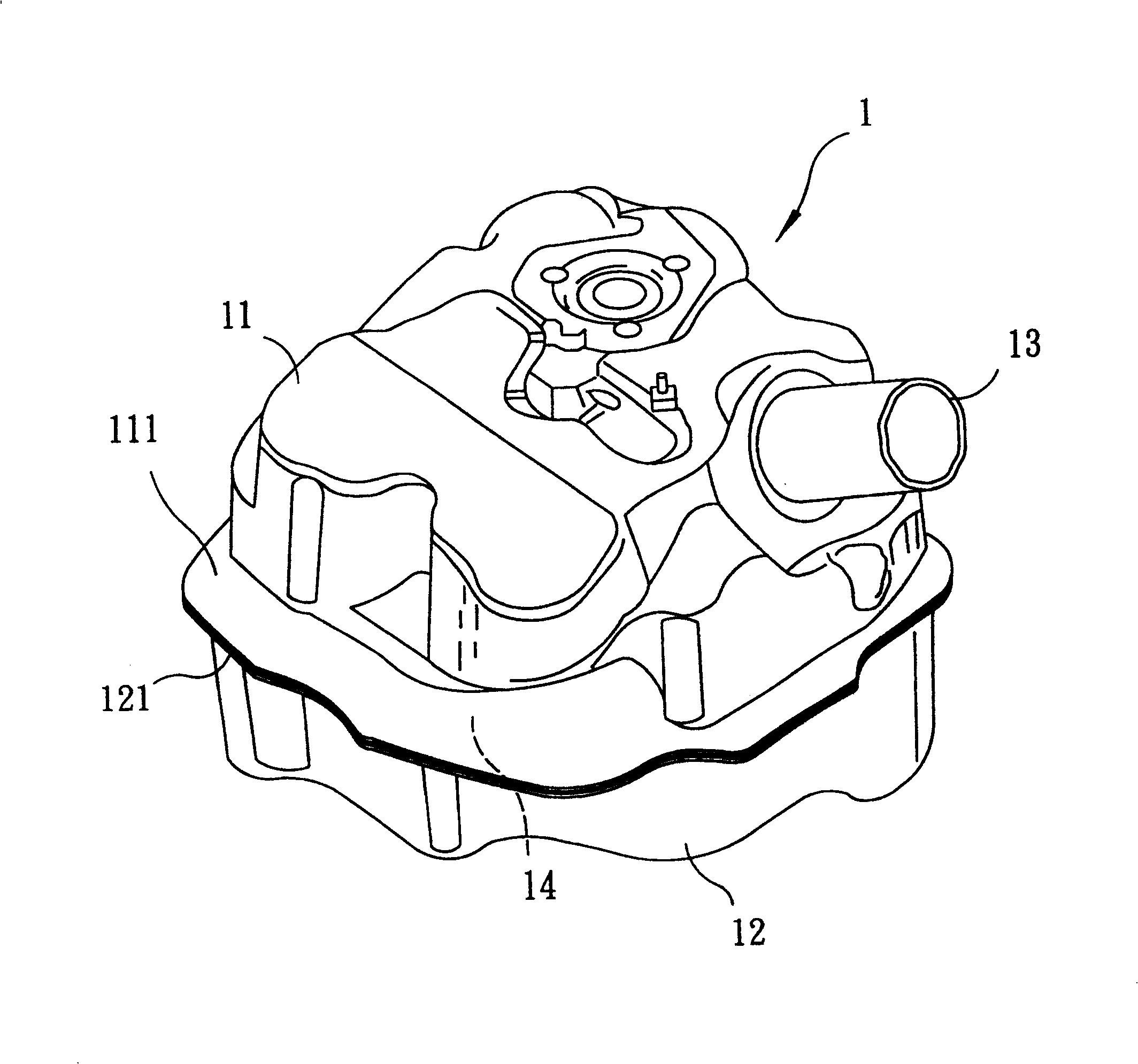
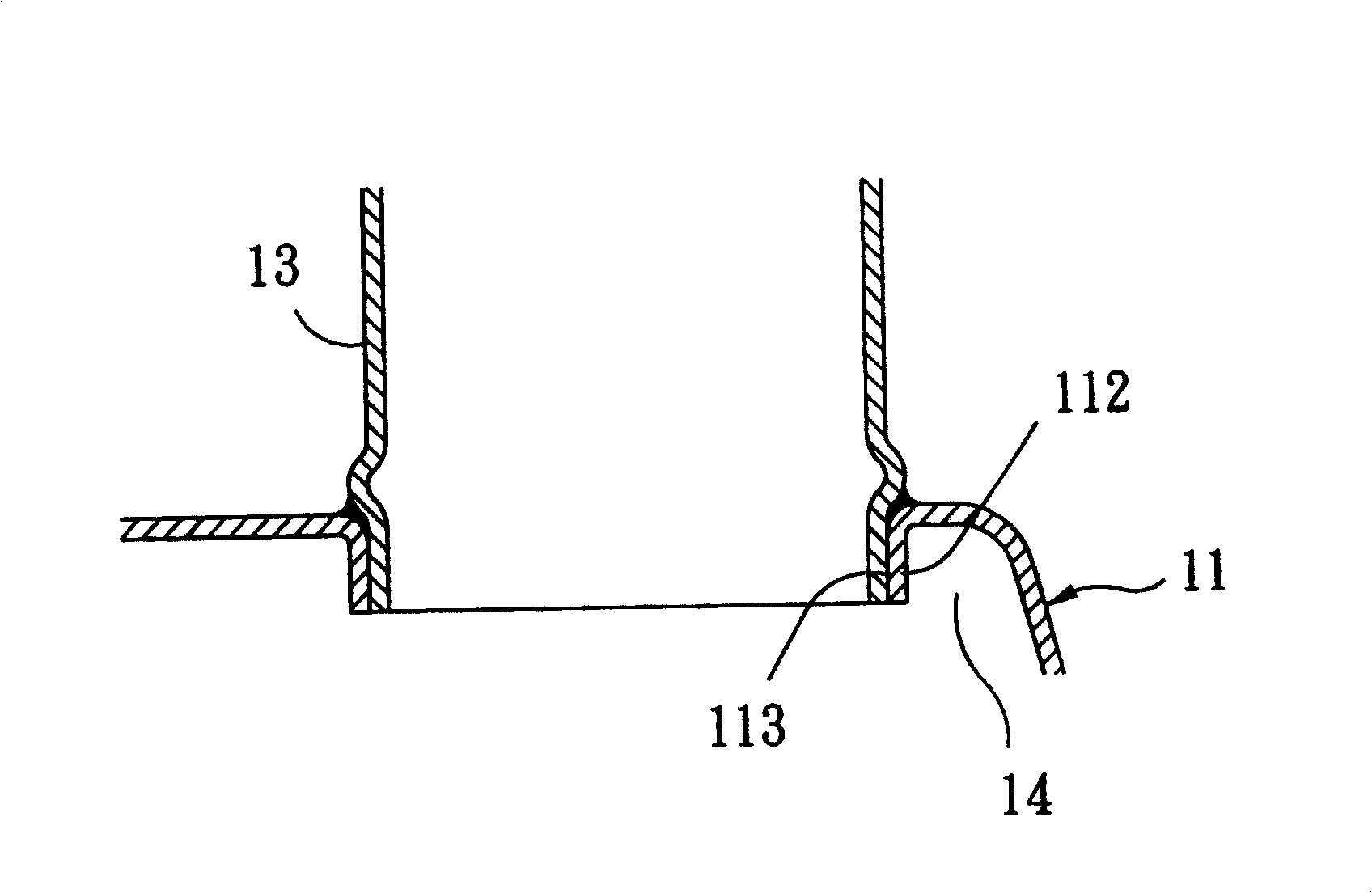
[0042] The upper case unit 31 has an upper case 311, an oil inlet 312 formed on the upper case 311, an outer flange 313 protruding from the upper case 311 around the periphery of the oil inlet 312, and a hollow annular oil pump fixing seat 314 .

[0043] Such as Figure 4 , Figure 6 As shown, the upper box body 311 includes a stepped mounting surface 315, an upright portion 310 and a flat portion 310' forming an outer periphery.

[0044] The stepped mounting surface 315 defines a mounting opening 317 that gradually widens outward.

[0045] The upright portion 310 and the plane portion 310' are connected to each other ...


PUM


Abstract

The present invention relates to cemented oil tank and its production process. The cemented oil tank as fuel oil storage for motor vehicle has simple production process, less operating damage, stable quality and low cost. The cemented oil tank includes upper tank unit, lower tank unit and connecting pipes, the upper tank unit has upper tank body, oil inlet and outer flange; and the lower tank unit has lower tank body. The production process includes the step of forming the upper tank body, upper tank unit and lower tank unit; the step of painting adhesive in the contact surface between the upper tank body and the lower tank body; and the step of heating inside heating furnace at 150-190 deg.c to cure and combine.

Description

Technical field [0001] The invention belongs to a motor vehicle fuel storage device and a manufacturing method thereof, in particular to a glued fuel tank and a manufacturing method thereof. Background technique [0002] In the locomotive manufacturing industry, the methods used to form the fuel tank of a locomotive are almost limited to welding technology. In the book'STRUCTURAL ADHESIVE JOINTS IN ENGINEERING' by ADAMS et al., pages 119-135 and Taiwan Patent Publication No. 332161, titled'Welding Seam Coating Method and Device', all have taught the use of argon welding, That is, the well-known methods of TIG welding, torch brazing and seam welding to form the fuel tank of a locomotive. [0003] In addition, Taiwan Patent Announcement No. 310290, titled "Method of manufacturing fuel cylinder from aluminum-plated steel plate, method of laser welding of aluminum-plated steel plate and laser welding material", also discloses the use of laser welding to make aluminum-plated steel loc...

Claims


Application Information

Patent Timeline
IPC IPC(8): B60K15/03B29C65/02B29C35/02
Inventor 姜志华薛英斌王俊杰廖英彦陈俊良
Owner METAL INDS RES & DEV CENT
Why Eureka
Try Eureka