Organic electroluminescent display panel
An electroluminescence and display panel technology, applied in electroluminescence light sources, electric light sources, circuits, etc., can solve the problems of intrusion and damage to organic electroluminescence display panels, etc.
- Summary
- Abstract
- Description
- Claims
- Application Information
AI Technical Summary
Problems solved by technology
Method used
Image
Examples
no. 1 example
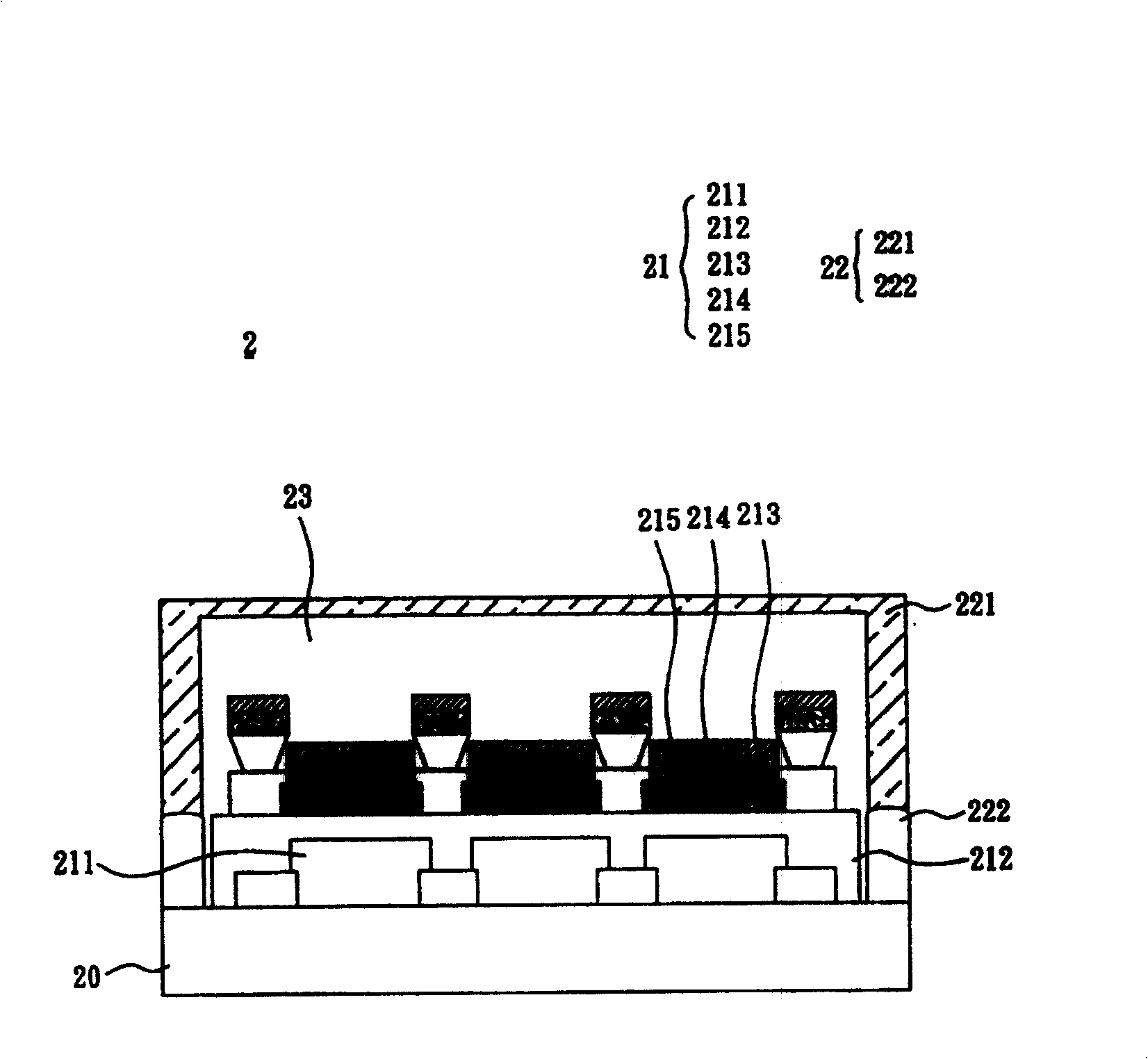
[0050] see figure 2 As shown, the organic electroluminescent display panel 2 according to the first embodiment of the present invention includes a substrate 20 , at least one organic electroluminescent element 21 and a packaging unit 22 .
[0051] The organic electroluminescent device 21 is disposed on the substrate 20 and includes an optical modulation layer 211 , a flat layer 212 , a first electrode 213 , at least one organic functional layer 214 and a second electrode 215 in sequence.
[0052] The encapsulation unit 22 is connected with the substrate 20 to form a closed space 23 , and the organic electroluminescent element 21 is located in the closed space 23 . Wherein, the packaging unit 22 can be packaged on the substrate 20 of the organic electroluminescent display panel 2 by a cover plate 221 matched with an adhesive 222, or a passivation layer; the cover plate 221 can be a cover Body type (such as figure 2 shown) or as a flat plate.
[0053] As mentioned above, in...
no. 2 example
[0061] see Figure 5 As shown, the organic electroluminescent display panel 3 according to the second embodiment of the present invention includes a substrate 30 , at least one organic electroluminescent element 31 , at least one barrier unit 33 and a packaging unit 32 .
[0062] The organic electroluminescent device 31 is disposed on the substrate 30 and includes an optical modulation layer 311 , a flat layer 312 , a first electrode 313 , at least one organic functional layer 314 and a second electrode 315 in sequence. In this embodiment, the organic electroluminescent element 31 may further include at least one barrier layer 316 disposed between the planar layer 312 and the first electrode 313 as described in the first embodiment, and as Figure 5 As shown, the barrier layer 316 may include a first barrier layer 317 and a second barrier layer 318 .
[0063] The barrier unit 33 is disposed on the substrate 30 ; the encapsulation unit 32 covers the barrier unit 33 and connect...
no. 3 example
[0067] see again Image 6 As shown, the organic electroluminescent display panel 4 according to the third embodiment of the present invention includes a substrate 40 , at least one organic electroluminescent element 41 and a packaging unit 42 .
[0068] The organic electroluminescent device 41 is disposed on the substrate 40 and includes an optical modulation layer 411 , a flat layer 412 , a first electrode 413 , at least one organic functional layer 414 and a second electrode 415 in sequence. In addition, the organic electroluminescent device 41 further includes at least one barrier layer 416 disposed between the flat layer 412 and the first electrode 413. As mentioned above, in this embodiment, the barrier layer 416 may include a first barrier layer 417 and a second barrier layer 418 .
[0069] The packaging unit 42 is connected with the substrate 40 to form a closed space 43, the organic electroluminescent element 41 is located in the closed space 43, and at least a part o...
PUM
 Abstract
Description
Claims
Application Information
 - R&D
- Intellectual Property
- Life Sciences
- Materials
- Tech Scout
- Unparalleled Data Quality
- Higher Quality Content
- 60% Fewer Hallucinations
Browse by: Latest US Patents, China's latest patents, Technical Efficacy Thesaurus, Application Domain, Technology Topic, Popular Technical Reports.
© 2025 PatSnap. All rights reserved.Legal|Privacy policy|Modern Slavery Act Transparency Statement|Sitemap|About US| Contact US: help@patsnap.com


