Auto-focusing device, electronic camera, and auto-focusing method
A technology of automatic focusing and equipment, applied in cameras, focusing devices, televisions, etc., can solve problems such as the accuracy of deterioration detection
- Summary
- Abstract
- Description
- Claims
- Application Information
AI Technical Summary
Problems solved by technology
Method used
Image


Examples
no. 1 example
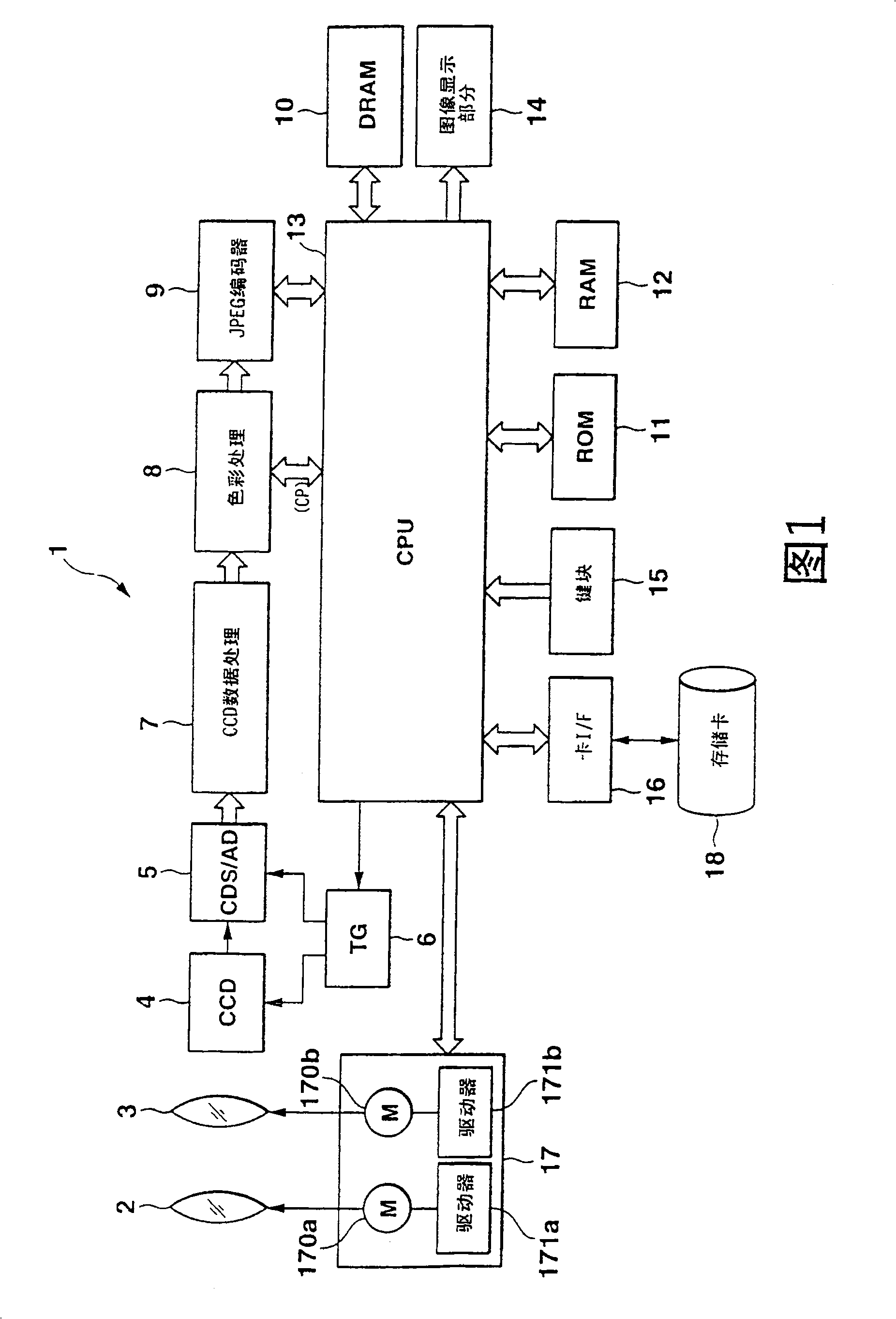
[0052]FIG. 1 is a schematic block diagram showing a digital camera (electronic camera) 1 according to a first embodiment of the present invention. The digital camera 1 has an AF function based on the contrast detection system used in the prior art as described above. Digital camera 1 includes focusing lens 2, zoom lens 3, CCD (image pickup device, image pickup device) 4, CDS / AD block 5, TG (timing signal generator) 6, CDD data preprocessing block 7, color processing (CP ) block 8, JPEG encoder 9, DRAM 10, ROM 11, RAM 12, CPU (processor) 13, image display section 14, key block 15, card interface (I / F) 16, and motor drive block 17. The card interface 16 is connected to a memory card 18 which is detachably inserted into a card slot formed in the camera body.
[0053] The focus lens 2 and the zoom lens 3 are formed of respective lens groups (not shown). The motor drive block 17 includes a focus motor 170a for driving the focus lens 2 along the optical axis of the camera, a zoom ...
no. 2 example
[0074]If the performance of the optical system including the focus lens 2 and the zoom lens 3 is such that the object can be brought into focus even when the focus lens 2 is slightly deviated from the correct focus position, and / or the vibration of the focus lens 2 during its movement can be kept To the lowest level, and thereby minimize or eliminate the influence of noise due to vibration on the AF estimate when determining the AF estimate, the AF control operation can be performed without the fine search operation described above. In this way, it is possible to detect the AF evaluation value maximum position while continuously moving the focus lens 2 and move the focus lens 2 by performing substantially the same rough search operation as described above to minimize the AF evaluation period (exposure time). Automatic focus is achieved by moving to the focus position used to bring the subject of the camera into focus.
[0075] The following will refer to Figure 5 To describe...
no. 3 example
[0084] In the third embodiment, the CPU 13 follows the timing described below, in the above reference for the first embodiment figure 2 In the coarse search operation in steps S2 to S6, or in the above reference for the second embodiment Figure 5 In the focus search operation of steps T2 to T6, a processing operation for exposure is performed in step S4 (T4).
[0085] Figure 7 is corresponding to image 3 A detailed timing chart of the autofocus control operation of the third embodiment. For the rough search (focus search) operation of the third embodiment, the exposure operation of the CCD 4 is performed in synchronization with the drive cycle (drive pulse) of the focus lens 2 in such a manner that the start timing of the AF evaluation cycle and the focus The timings at which the motor 170a drives the focus lens 2 always coincide with each other. Although the operation of driving the focus lens 2 and the exposure operation of the CCD 4 are performed at different cycles,...
PUM
 Abstract
Description
Claims
Application Information
 - R&D
- Intellectual Property
- Life Sciences
- Materials
- Tech Scout
- Unparalleled Data Quality
- Higher Quality Content
- 60% Fewer Hallucinations
Browse by: Latest US Patents, China's latest patents, Technical Efficacy Thesaurus, Application Domain, Technology Topic, Popular Technical Reports.
© 2025 PatSnap. All rights reserved.Legal|Privacy policy|Modern Slavery Act Transparency Statement|Sitemap|About US| Contact US: help@patsnap.com