Substrate disposing device and method

A substrate processing device and substrate technology are applied in the directions of transportation and packaging, conveyor objects, optics, etc., which can solve the problems of difficulty in adjusting the friction force between the substrate 90 and the rotating brush, difficulty in adjusting the angle, and poor cleaning, etc. Costs and maintenance costs, simplification of conveying routes, and the effect of preventing a reduction in cleaning effect

Inactive Publication Date: 2008-11-12
K C TECH
View PDF4 Cites 0 Cited by
  • Summary
  • Abstract
  • Description
  • Claims
  • Application Information

AI Technical Summary

Problems solved by technology

[0039] In addition, the distance between the rotating brushes RB1-RB4 and the base plate 90 is measured by the operator with naked eyes or mechanical measuring means, so it is inaccurate and difficult to adjust the frictional force between the base plate 90 and the rotating brush. Poor cleaning problem occurs
[0040] In addition, it is difficult to adjust the angles of the air knives AN1 and AN2 of the drying section 53 in the surface treatment section 50, so that mist reattaches to the dried substrate, causing problems such as substrate contamination.

Method used


Image

  • Substrate disposing device and method
  • Substrate disposing device and method
  • Substrate disposing device and method

Examples


Embodiment 1

[0077] FIG. 6 is a block diagram of an embodiment of the substrate processing apparatus of the present invention; FIG. 7 is a simplified perspective view of an embodiment of the substrate processing apparatus.

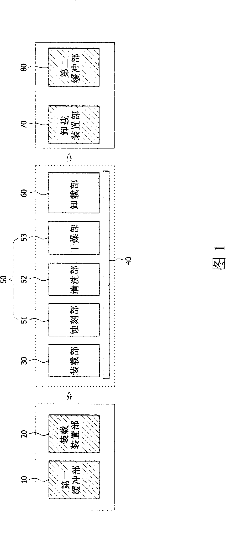
[0078] As shown in the figure, an embodiment of the substrate processing apparatus of the present invention includes: a buffer unit 100 for temporarily storing substrates; a loading and unloading unit 300 for loading substrates transported from the buffer unit 100 by a transport device 200, or unloading (Unloading) the substrates that have completed surface treatment, and transport the processed substrates to the buffer unit 100 by the transport device 200; the first conveyor 400 transports the substrates loaded in the above-mentioned loading and unloading unit 300; the lifting unit 500, move the substrate transported by the first conveyor 400 downward, and load it on the second conveyor 600, so that the substrate is transported to the loading and unloading part 300 aga...

Embodiment 2

[0096] In the first embodiment above, the surface treatment unit 700 that directly processes the surface of the substrate is set to process the substrate conveyed by the second conveyor 600, but it may also be set to separate a part of the functions of the surface treatment unit 700 and It is arranged on the first conveyor 400 to perform related processing on the first conveyor 400 .

[0097] That is, like the first embodiment above, when the surface treatment unit 700 includes etching, cleaning, and drying the substrate, the etching unit 710 can be arranged on the first conveyor 400, and the substrate moved by the first conveyor 400 can be processed. After the etching process, the etched substrate is moved down and loaded onto the second conveyor 600 by the lifting part 500, and finally, when the substrate moved by the second conveyor 600 passes through the cleaning unit 720 and the drying unit 730 in sequence, Wash and dry.

[0098] By separating part of the functions of th...

Embodiment 3

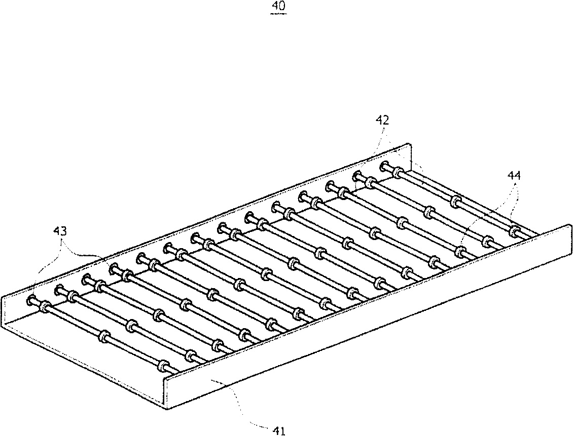
[0103] Figure 8 It is a perspective view of an embodiment of the above-mentioned second conveyor 600 .

[0104] As shown in the figure, the second conveyor 600 in the present invention includes: a supporting table 610 with an upwardly curved surface on both sides of the moving direction of the substrate; Bearings 630; a plurality of light weight shafts 620 rotatably coupled to the upwardly curved surface of the above-mentioned support platform 610 through the plurality of bearings 630;

[0105] Figure 9 is a cross-sectional view of one embodiment of the shaft 620 described above.

[0106] As shown in the figure, the shaft 620 of the second conveyor 600 in the present invention includes: a tubular body 621; an intermediate metal layer 622 attached to the outer peripheral surface of the above-mentioned body 621; layer 623 ; one end thereof is inserted into both sides of the body 621 , and the other end forms two ends 624 combined with the bearing 630 in the upward bending p...


PUM


Abstract

The invention relates to a substrate disposing device and method. The substrate disposing device comprises a loading and unloading part for loading the substrates to be surface treated or unloading the substrates having been surface treated; a first feeder for feeding the substrates in the above-mentioned loading and unloading part; a lifting part for carrying down the substrates fed by the first feeder; a second feeder for feeding the substrates loaded by the lifting part to the loading and unloading part; a surface treating part for carrying out surface treatment to the substrates fed by the second feeder. The invention with the above-mentioned structure centralizes loading position and unloading position of substrates, loads and unloads substrates with a single device, thus simplifying the feeding path of substrates to the substrate device, increasing service efficiency of clean room and reducing equipment cost and maintenance cost of the clean room.

Description

technical field [0001] The invention relates to a substrate processing device and a processing method thereof, in particular to a device and a processing method thereof for processing surfaces of objects to be processed such as semiconductor wafers and flat panel display substrates. Background technique [0002] In general, substrate processing equipment for processing the surface of objects to be processed such as semiconductor wafers and flat panel displays is divided into etching equipment, cleaning equipment, stripping equipment (Stripper), developing equipment (Developer), and the like. [0003] The structure of the above-mentioned processing device is similar, and it is set in a clean room that has been cleaned of fine dust. [0004] FIG. 1 is a structural diagram of an embodiment of a conventional substrate processing apparatus. [0005] As shown in the figure, the existing substrate processing apparatus includes a first buffer unit 10 provided with a substrate stora...

Claims


Application Information

Patent Timeline
Patent Type & Authority Patents(China)
IPC IPC(8): H01L21/67H01L21/677H01L21/00
CPCG02F1/13H01J9/24H01L21/67126H01L21/677
Inventor 俞龙根权五炅金珍玉崔成元姜信载林锡泽徐奉揆
Owner K C TECH
Why Eureka
Try Eureka