Multipath control valve used in soft water treating equipment

A multi-way control valve and treatment equipment technology, applied in multi-way valves, mechanical equipment, valve devices, etc., can solve the problems of small cross-sectional area of ​​through holes, reduced water flow output, and reduced water quality of water treatment effluent, etc. The effect of large water treatment flow, ensuring effluent quality and improving effluent quality

Inactive Publication Date: 2008-11-26
陈锋
View PDF7 Cites 0 Cited by
  • Summary
  • Abstract
  • Description
  • Claims
  • Application Information

AI Technical Summary

Problems solved by technology

Its shortcomings: First, because each through hole is limited by its structural size, the cross-sectional area of ​​the through hole is small, which seriously affects the output of the water flow in the through hole
The end face of the movable valve plate is provided with a radial blind hole from the central hole to the edge, because the blind hole should correspond to the communication position of the plurality of through holes provided on the fixed valve plate, so the diameter is limited. The indexing angle to the opening of the blind hole should not be too large, resulting in a reduction in the flow cross-sectional area of ​​the blind hole. In actual work, water can only enter from the center hole and the fan-shaped blind hole connected to it, directly causing Reduction in water flow output
Seriously affected people's demand for large-flow water in production or life
The second is that when the blind hole provided on the end face of the movable valve plate is switched to the working position, the blind hole is easily communicated with two adjacent through holes of which there are multiple through holes on the fixed valve plate. The raw water enters the water purification channel and is directly discharged outward, which seriously affects the quality of water treatment and purification.
The third is that during the backwashing work, due to the limitation of the small cross-sectional area of ​​the through hole of the fixed valve plate, the flow rate of backwashing water flowing through the through hole is obviously less than the normal working water flow rate. The flow rate is small and the flushing is not thorough, which will cause the filter material to be clogged, hardened or invalid, directly resulting in the decline of the water quality of the water treatment
[0003] In addition, the control valves used in softened water treatment equipment in the prior art can only be installed with single-function control valves when people filter water, fix bed countercurrent regeneration softening, floating bed softening or fixed bed downstream regeneration softening treatment. Filter valves, fixed bed countercurrent regeneration softening valves, floating bed softening valves or fixed bed downstream regeneration softening valves, special valves significantly increase the production cost of control valves for softening water treatment equipment

Method used


Image

  • Multipath control valve used in soft water treating equipment
  • Multipath control valve used in soft water treating equipment
  • Multipath control valve used in soft water treating equipment

Examples


Embodiment 1

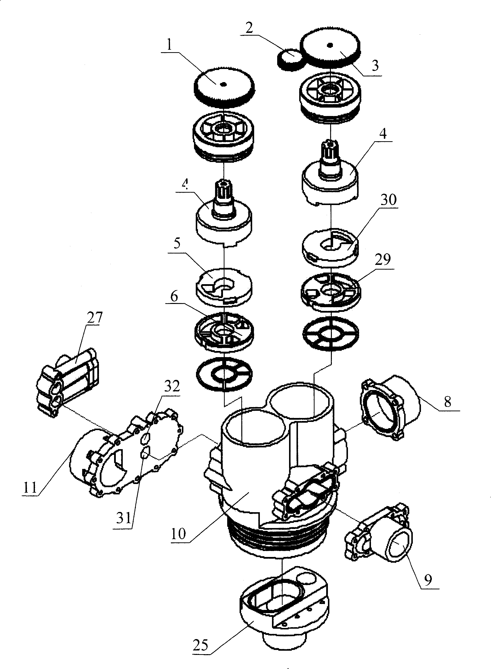
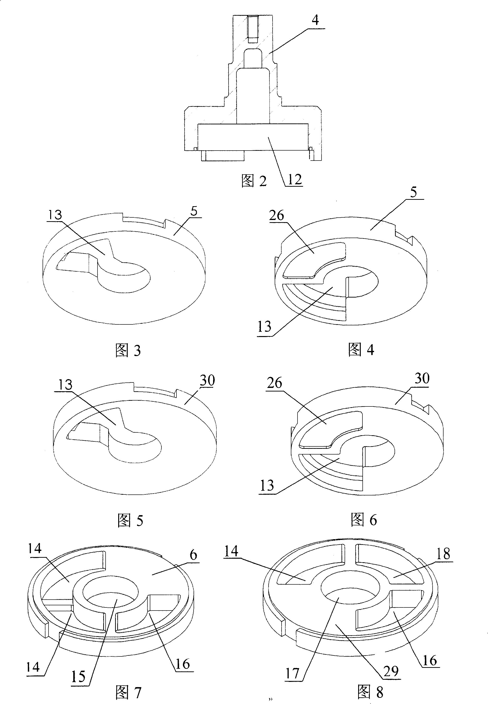
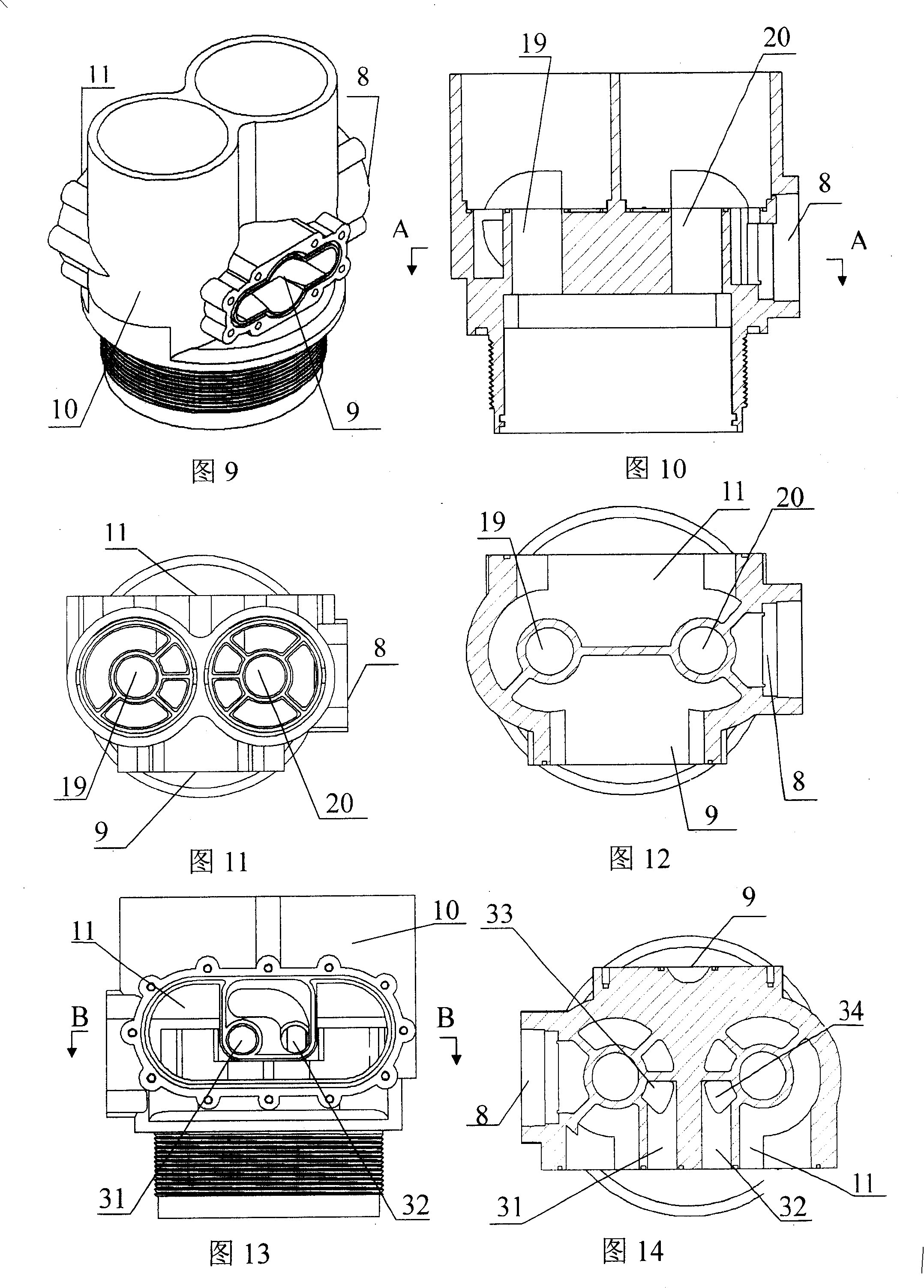
[0089] Embodiment one, figure 1 ~ Figure 3, Figure 5, Figure 7 ~ Figure 17. This multi-way control valve for softening water treatment equipment mainly includes a valve body connected with raw water inlet, clean water outlet and sewage outlet, and a valve core connected to the valve stem is placed in the valve body; it is composed of two valves The spool connected by the rod 4 is placed in the left and right spool cavities of the valve body 10; Combination sealing structure; the end faces of the two movable valve plates 5, 30 and the end faces of the valve stem 4 are respectively fitted with grooves and protrusions (as shown in Fig. 2-Fig. 6); in order to increase the water flow and In the flow space, a volume groove 12 is provided on the mating end faces of the two valve stems 4; a fan-shaped channel extending radially from the central hole to its edge is provided on the end faces of the moving valve plates 5 and 30. Hole 13 (shown in Figure 3 and Figure 5). On the end fac...

Embodiment 2

[0090] Embodiment two, figure 1 - Figure 2, Figure 4, Figure 5, Figure 9-Figure 17, Figure 21-Figure 22 shown. The structure of the present invention is the same as that of the first embodiment and will not be described in detail. Its difference is: at the salt inlet 31 and 32 place of described valve body, be connected with ejector 27. On the end face where the left movable valve plate 5 and the fixed valve plate 6 are joined, a guide blind hole 26 (shown in FIG. 4 ); On the end face between the holes 16, fan-shaped salt holes 28 ( Figure 21 Shown); On the end face between the fan-shaped water inlet hole 14 and the drain hole 16, the fixed valve plate 29 on the right is provided with a salt hole 23 ( Figure 22 shown). It not only constitutes a fixed bed countercurrent regeneration softening valve for softening water treatment equipment.

Embodiment 3

[0091] Embodiment three, figure 1 -Figure 2, Figure 4, Figure 5, Figure 9-Figure 16, Figure 18- Figure 22 shown. The structure of the present invention is the same as that of the second embodiment and will not be described in detail. The difference is that the upper and lower water distribution holes 15 and 17 on the left and right fixed valve plates pass through the upper water distribution hole 19 and the lower distribution water hole 20 of the left and right valve core chambers of the valve body respectively, and connect with the valve body. The lower water distributor connection hole 21 that is connected with the water distribution connector 25 is connected with the upper water distributor connection hole 36 (Fig. 18- Figure 20 shown). That is, it constitutes a floating bed softening valve for water treatment equipment.


PUM


Abstract

The invention discloses a multi-path control valve for treating soft water, formed by two movable valves (5, 30) and stable valves (6, 29) in a valve (10) while their ends are sealed and combined. The ends of the movable and stable valves are arranged with through holes communicated with a water inlet, a sewage outlet, a pure water outlet, a salt let, and upper and lower distributor connecting holes on former valve, via channels and connected distributor connectors (25) in the valve. Compared with present technique, the invention can improve the water treated flux more than 25t/h to improve water quality. And the invention can change the valves and distributor connectors with different through hole positions to be used as filter valve, fixed bed reverse regenerate soft valve or the like, with four functions, to reduce 55% cost.

Description

(1) Technical field: [0001] The invention relates to a waterway control device; in particular, it relates to a multi-way control valve for softened water treatment equipment. (two) background technology: [0002] In the prior art, the control valve used for the small-flow softening water treatment equipment with the end-face sealing structure in production or life (the water flow rate is generally ≤10T / h), the valve core is usually connected by a pair of end faces that are mated and sealed. It consists of a moving valve and a fixed valve. By rotating the moving valve, the output of the water flow in the valve core can be controlled and the direction, time and flow of the water output can be changed, so as to backwash the filter material (such as activated carbon, quartz sand) respectively. , positive flushing or normal operation to achieve water purification; or perform backwashing, salt absorption, positive flushing, salt tank filling or normal operation on the filter mater...

Claims


Application Information

Patent Timeline
Patent Type & Authority Patents(China)
IPC IPC(8): F16K11/10
Inventor 王承丰
Owner 陈锋
Why Eureka
Try Eureka