Air flotation cyclone contactor and air flotation cyclone system

A contactor and air flotation technology, applied in chemical instruments and methods, flotation water/sewage treatment, water/sewage multi-stage treatment, etc., can solve problems affecting the process flow, low efficiency, pollution, etc., and achieve large treatment flow , increase the processing capacity, and improve the separation effect

Active Publication Date: 2020-09-25
CHINA UNIV OF PETROLEUM (EAST CHINA)
View PDF6 Cites 0 Cited by
  • Summary
  • Abstract
  • Description
  • Claims
  • Application Information

AI Technical Summary

Problems solved by technology

From this process, it can be found that in the traditional air flotation separation technology, it mainly relies on the diffusion motion of the bubble itself to collide with the suspended matter, which is inefficient.
[0004] In industrial applications, in order to improve the contact effect between suspended solids and air bubbles, flocculants are generally used to form suspended solids into flocs. One is to combine suspended solids with each other to increase the floating speed. It has a wide distribution and has a stronger ability to trap air bubbles, but the use of flocculants is equivalent to adding new impurities to the sewage, which may cause new pollution or affect the subsequent process, so there are also disadvantages

Method used


Image

  • Air flotation cyclone contactor and air flotation cyclone system
  • Air flotation cyclone contactor and air flotation cyclone system

Examples


Embodiment 1

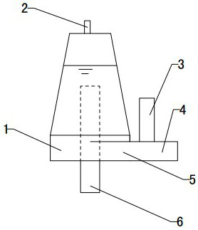
[0025] Reference attached figure 1 : Air-floating cyclone contactor, including a cone 1, the side wall of the cone 1 is connected to a tangentially arranged liquid inlet pipe 5, the top of the cone 1 is provided with an exhaust port 2, and the bottom is provided with a liquid outlet pipe 6. Two branch pipes are provided at the outer end of the liquid inlet pipe 5.

[0026] The cone 1 is a structure with a narrow top and a wide bottom, and the liquid inlet pipe 5 is arranged on the lower side of the cone 1. The top of the cone 1 is provided with an exhaust cavity, and the top of the exhaust cavity is connected with an exhaust port 2. The outlet pipe 6 is arranged concentrically with the cone 1, the upper part of the outlet pipe 6 extends into the inside of the cone 1, and the top of the outlet pipe 6 is arranged on the upper part of the cone 1, and the top of the outlet pipe 6 is higher than the cone 1. The horizontal centerline of the shaped cylinder 1.

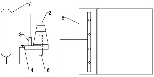
[0027] Reference figure ...

Embodiment 2

[0034] The liquid outlet pipe 6 is arranged concentrically with the cone barrel 1, the upper part of the liquid outlet pipe 6 extends into the inside of the cone barrel 1, and the top of the liquid outlet pipe 6 is arranged at the lower part of the cone barrel 1. The top of the liquid outlet pipe 6 is set at the lower part of the cone 1, compared with the top of the liquid outlet pipe 6 arranged on the upper part of the cone 1, it can have a longer residence time while avoiding bubble-suspension polymerization The substance moves to the outer wall of the outlet pipe 6 under the action of centrifugal force, and cannot leave the inner cavity of the cyclone contactor. Other settings and working principles are the same as the first embodiment.

Embodiment 3

[0036] The liquid inlet pipe 5 is arranged on the central side of the cone 1. The liquid inlet pipe 5 is arranged on the side of the middle of the cone 1 to allow the liquid to flow from top to bottom. This method can increase the residence time of the bubbles in the contactor and increase the concentration of the bubbles in the contactor. Other settings and working principles are the same as the first embodiment.


PUM


Abstract

An air-flotation swirling flow contactor and an air-flotation swirling flow system belong to the technical field of air floatation separation. The contactor is characterized by comprising a conical barrel (1), and the side wall of the conical barrel (1) is connected to a tangentially-arranged liquid inlet pipe (5); the top of the conical barrel (1) is provided with an air outlet (2), and the bottom is provided with a liquid outlet pipe (6); and the outer end part of the liquid inlet pipe (5) is provided with two branch pipes. According to the technical scheme, a swirling flow way is used to mix gas-dissolved water and sewage together, the mixed liquid makes low-intensity swirling motion in the contactor, and collision between bubbles and suspended particles is caused because of the movement of the suspended particles and the bubbles and change of a streamline, so that the inertial collision and the centrifugal sedimentation collision of the bubbles and suspended matters are effectivelyenhanced, the contacting effect of the bubbles and the suspended matters is promoted, the separation effect of air floatation is improved, and the handling capacity is substantially improved.

Description

Technical field [0001] An air floatation cyclone contactor and an air floatation cyclone system belong to the technical field of air floatation separation. Background technique [0002] At present, air flotation is still a widely used technology in sewage treatment. The principle of air flotation is to form a large number of dispersed tiny bubbles in the sewage, so that the tiny bubbles collide with the suspended matter in the sewage and adhere to the suspended matter to form a polymer. The apparent density of the polymer is less than water, so the polymer can float to the water surface. Separate from the water to purify the sewage. Since the apparent density of the polymer formed by bubbles and suspended solids is also lower than that of suspended solids, air flotation can increase the floating speed of suspended solids with a density less than water. [0003] The collision rate of bubbles and suspended matter directly affects the effect of air flotation separation. The higher t...

Claims


Application Information

Patent Timeline
Patent Type & Authority Patents(China)
IPC IPC(8): C02F1/24C02F1/38C02F9/02C02F1/52
CPCC02F1/24C02F1/38C02F1/52C02F9/00
Inventor 孙治谦周衍涛刘伯川王振波李强朱丽云
Owner CHINA UNIV OF PETROLEUM (EAST CHINA)
Why Eureka
Try Eureka