Abbe error correction system and method

A technology of Abbe error and positioning system, applied in general control system, control/adjustment system, program control, etc., can solve problems such as limitation and correction speed limitation, and achieve the effect of reducing cost and manufacturing cost

Inactive Publication Date: 2008-11-26
ELECTRO SCI IND INC
View PDF12 Cites 0 Cited by
  • Summary
  • Abstract
  • Description
  • Claims
  • Application Information

AI Technical Summary

Problems solved by technology

The correction speed of the Trumper et al. system is limited by the bandwidth of the linear-level system, and thus has a quality vs. bandwidth limitation similar to that of the stack-level positioning system

Method used


Image

  • Abbe error correction system and method
  • Abbe error correction system and method
  • Abbe error correction system and method

Examples


Embodiment Construction

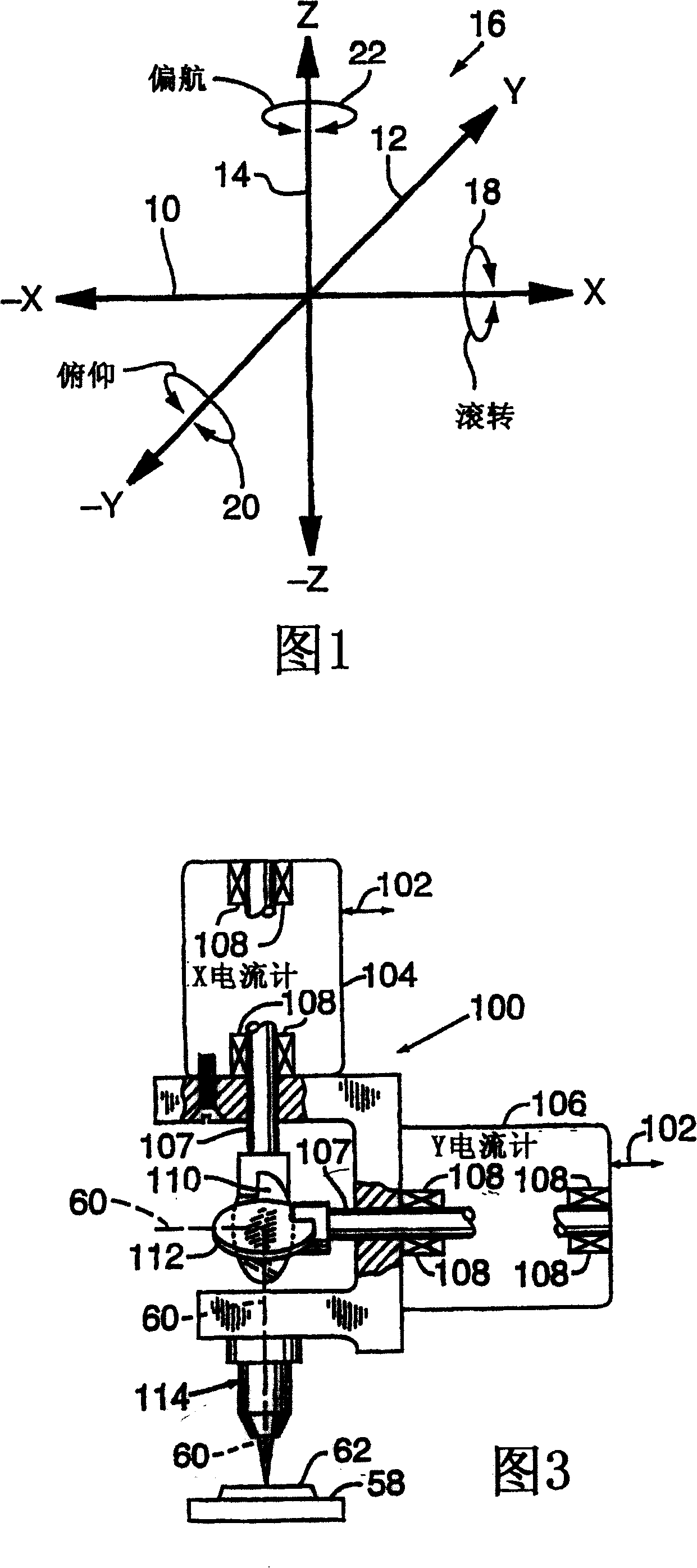
[0086] A typical tool application utilizing the positioner system 50 and including Abbe error correctors is to laser cut holes (such as blind via holes) in a multilayer ECB or other workpiece 62 . Multilayer ECBs are typically manufactured by laying out, stacking together, laminating, and compressing multiple 0..05-0..08mm thick circuit board layers. Each layer contains a different interconnect pad and conductor pattern which, after compression, constitutes a composite electrical component mounting and interconnect assembly. The component and conductor density trends of ECBs are increasing along with the trends of integrated circuits. Therefore, the positioning accuracy and size tolerance of the holes in the ECB are proportionally increased.

[0087] Unfortunately, the compression step causes expansion and dimensional changes, thus resulting in changes in the scale factor and orthogonality of the ECB. Additionally, when multiple ECBs (workpiece 152) are connected to the slow...


PUM

PropertyMeasurementUnit
porosityaaaaaaaaaa

Abstract

The present invention preferably employs non-contact, small-displacement, capacitive sensors (124, 128, 130, 131, 132) to determine Abbe errors due to the pitch (20), yaw (22), or roll (18) of a near linear mechanical stage (56, 58) that are not indicated by an on-axis position indicator, such as a linear scale encoder or laser interferometer. The system is calibrated against a precise reference standard so the corrections depend only on sensing small changes in the sensor readings and not on absolute accuracy of the sensor readings. Although the present invention is preferred for use in split-axis positioning systems (50) with inertially separated stages (56, 58), the invention can be employed in typical split-axis or stacked stage systems to reduce their manufacturing costs.

Description

[0001] This application derives priority from US Provisional Patent Application No. 60. / 175,993, filed January 11, 2000. technical field [0002] The present invention relates to a system and method for locating the relative target position of one or more "tools", such as laser beams or other radiation beams, on one or more workpieces, and the present invention particularly Refers to a system that accurately compensates for the Abbe error (Abbe error) associated with the movement of one or more stages of beam positioning systems. Background technique [0003] Various techniques utilize tools to micromachine or place patterns or materials at targeted locations on a workpiece. For example, micro-sized hole punches can be used to drill holes in thin metal plates; lasers can be used to precision machine or selectively etch metallic, crystalline, or amorphous samples; injected into the integrated circuit. All of the above-mentioned processes have a common need to quickly and ac...

Claims


Application Information

Patent Timeline
Patent Type & Authority Patents(China)
IPC IPC(8): G05B19/39G03F7/20B23K26/04G05B19/404G05D3/12H05K3/00
CPCB23K26/04G03F7/70725G05B19/404G03F7/70716H05K3/0008B23K26/043G05B19/39
Inventor D·R·卡特勒
Owner ELECTRO SCI IND INC
Why Eureka
Try Eureka