
Mark point matching method for point-cloud registration in 3D scanning system

A technology of three-dimensional scanning and point cloud splicing, which is applied in the direction of using optical devices, image data processing, measuring devices, etc., can solve problems such as inability to accurately locate, cannot guarantee matching relationships, and lack of criteria for finding corresponding relationships, and achieves clear thinking, Avoid complex operations and achieve convenient effects

Inactive Publication Date: 2008-12-17
HAIAN COUNTY SHENLING ELECTRICAL APPLIANCE MFG +1
View PDF3 Cites 1 Cited by
  • Summary
  • Abstract
  • Description
  • Claims
  • Application Information

AI Technical Summary

Problems solved by technology

However, this method cannot accurately locate, lacks effective criteria for finding corresponding relationships, and cannot guarantee correct matching relationships

Method used


Image

  • Mark point matching method for point-cloud registration in 3D scanning system
  • Mark point matching method for point-cloud registration in 3D scanning system
  • Mark point matching method for point-cloud registration in 3D scanning system

Examples


Embodiment Construction

[0032] A Marker Point Matching Method for Point Cloud Stitching in a 3D Scanning System

[0033] Step 1: Dynamically divide the first point cloud marker point set at the beginning of successive scans according to the spatial coordinates and distance values ​​{M i}(i=0, 1,...n), forming layer-by-layer nesting, the division criterion is: set the center layer M 0 , the side length of the cube is set to L, and the center layer data is used as the reference coordinate system. Then, the layer is added dynamically, the side length of the second layer cube is 3L, the side length of the third layer cube is 5L, and so on. The side length of the i-layer cube is 2i+1, forming layer nesting;

[0034] Step 2: a) Set the first point cloud at the beginning of successive scans as the benchmark, and use the current data layer M a Point to the data layer where the overlapping area of ​​the first point cloud of the successive scans and the second point cloud of the successive scans is located, ...


PUM


Abstract

A method for quick match of the cloud point starts with sequentially scanning the No. 1 width point mark set based on the space coordinate and gap value, dynamically dividing the layer to form the embedding structure, based on the No. 1 point to progressively scanning and matching the points, predicting the data area conforming to the actual movement rules before searching identification using area data matching, adding corresponding data layer after matching calibration treatment, for further prediction, dynamically modifying the data layer with continuous memory and optimization, with the scanning and matching continuing. .

Description

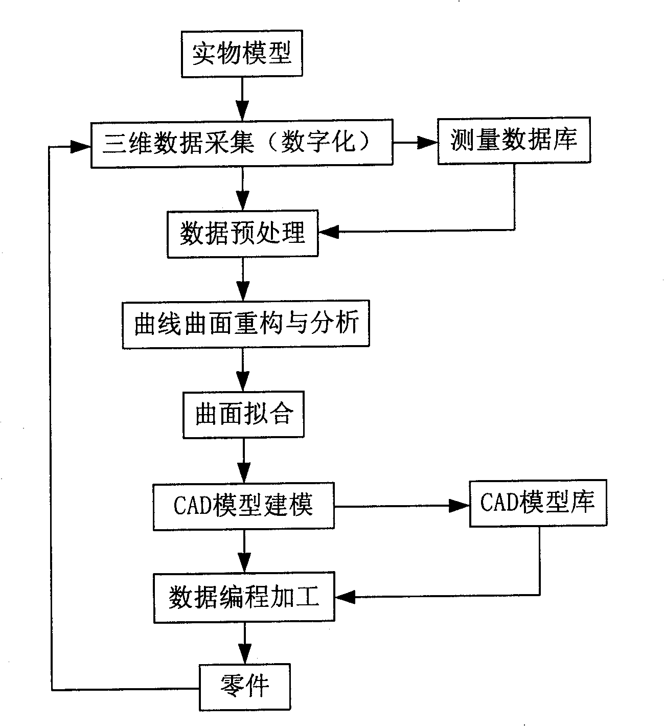
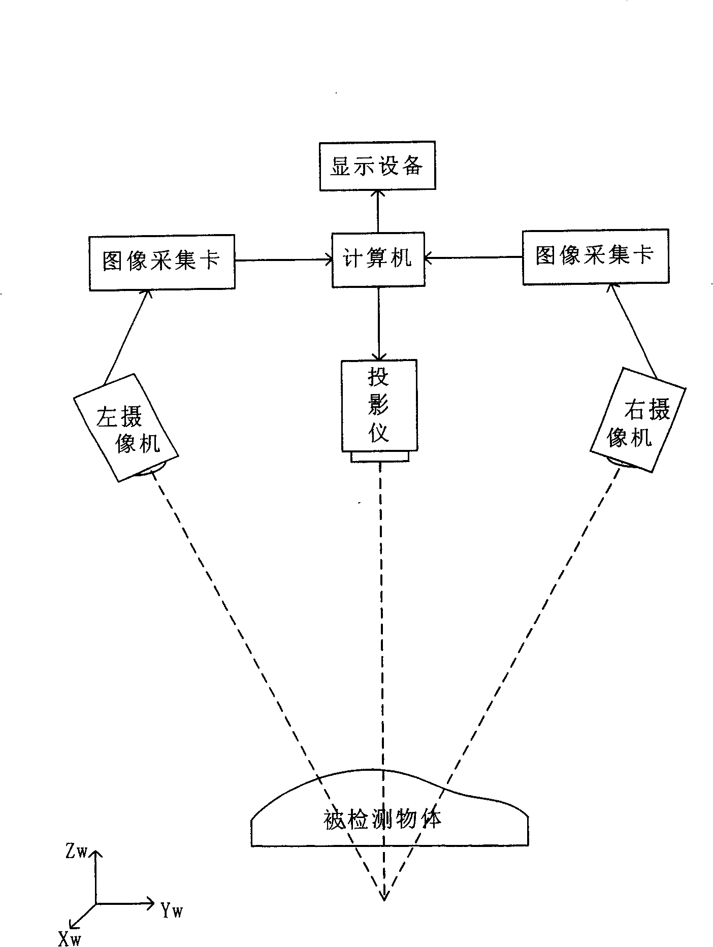
technical field [0001] reverse engineering technology (attached figure 1 ) is an advanced manufacturing technology that uses 3D digital measuring instruments to digitize products (physical models or prototypes), collects three-dimensional coordinate points of the model, uses CAD software to model, and finally manufactures products. It generally includes four basic links: three-dimensional shape Detection and conversion (acquisition of physical data), data preprocessing (point cloud processing, recognition, multi-view splicing), establishment of CAD model (surface reconstruction), CAM part molding. The present invention mainly relates to the use of a three-dimensional scanning system for the same object in the data preprocessing process of reverse engineering (attached figure 2 ) is a landmark matching method when the multi-view point cloud obtained by using the multi-view label positioning method is spliced. In engineering practice, point cloud measurement data is generally...

Claims


Application Information

Patent Timeline
Patent Type & Authority Patents(China)
IPC IPC(8): G06T7/00G01B11/00
Inventor 达飞鹏朱春红
Owner HAIAN COUNTY SHENLING ELECTRICAL APPLIANCE MFG
Learn More