Measuring method of optical transmission function and its device

An optical transfer function and measuring device technology, which is applied to measuring devices, optical instrument testing, and optical performance testing, etc., can solve the problems of low photometric efficiency, troublesome mathematical processing of rectangular gratings, and difficulty in producing sinusoidal gratings, and achieves high photometric efficiency, Create effects that are easy and simple to configure

Inactive Publication Date: 2008-12-24
CHANGCHUN INST OF OPTICS FINE MECHANICS & PHYSICS CHINESE ACAD OF SCI
View PDF5 Cites 0 Cited by
  • Summary
  • Abstract
  • Description
  • Claims
  • Application Information

AI Technical Summary

Problems solved by technology

[0004] The present invention aims at the low photometric efficiency caused by the combination of the bromine tungsten light source and the narrow-band filter in the background technology, the difficulty in making the sinusoidal grating, and the troublesome mathematical processing of the rectangular grating. The device generates a sinusoidal light intensity image, performs optical transfer function measurement, and provides a measurement device for optical transfer function

Method used


Image

  • Measuring method of optical transmission function and its device
  • Measuring method of optical transmission function and its device
  • Measuring method of optical transmission function and its device

Examples


Embodiment Construction

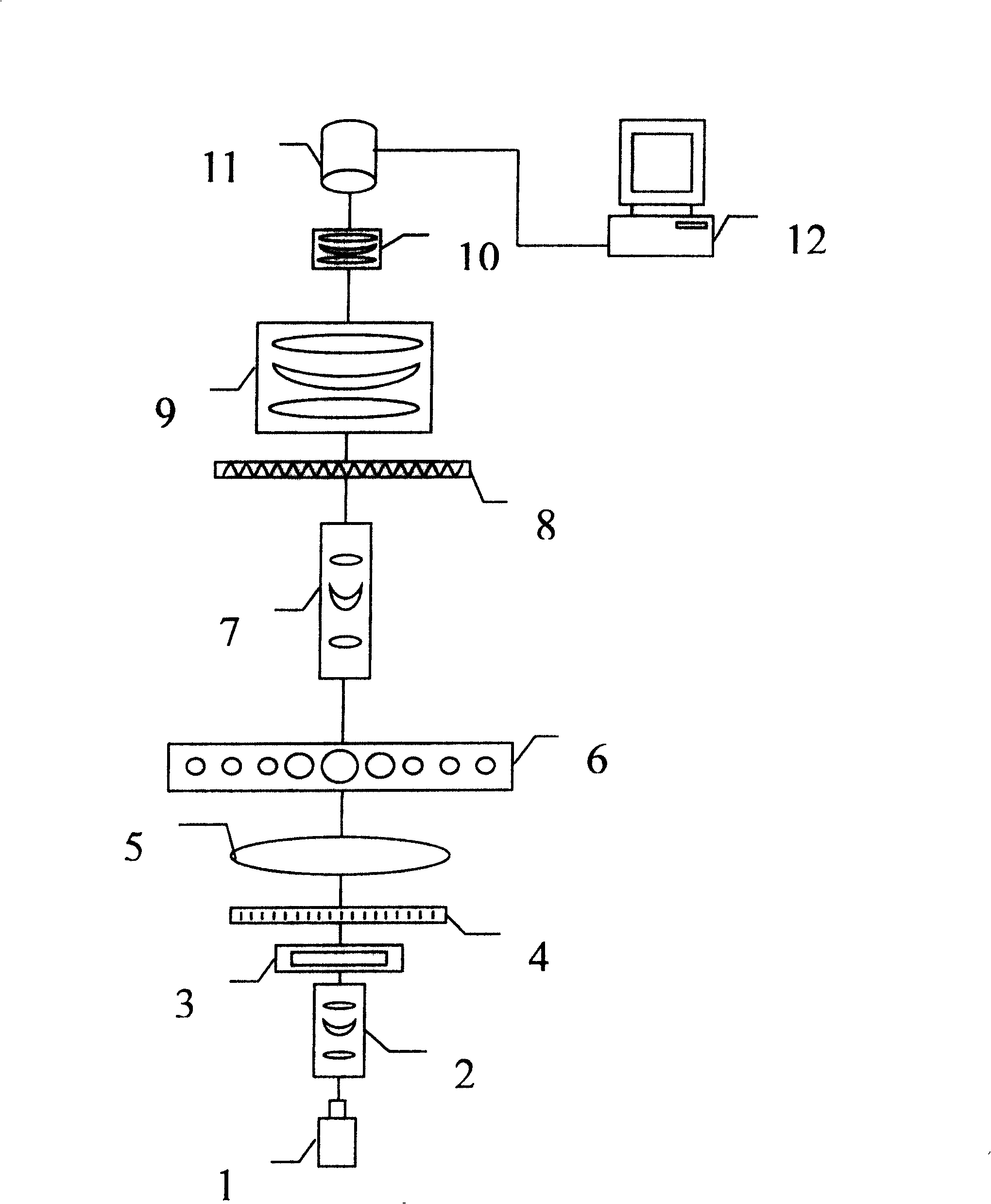
[0020] Such as figure 1 , figure 2 , image 3 , Figure 4 Shown:

[0021] The present invention includes a laser 1, a beam shaping system 2, a light reduction plate 3, a rectangular grating 4, a Fourier transform lens 5, an optical spatial filter 6, a zoom collimation system 7, a restrictive aperture 8, an optical system to be tested 9, and a variable magnification Amplifying system 10, area array CCD11, computer processing system 12.

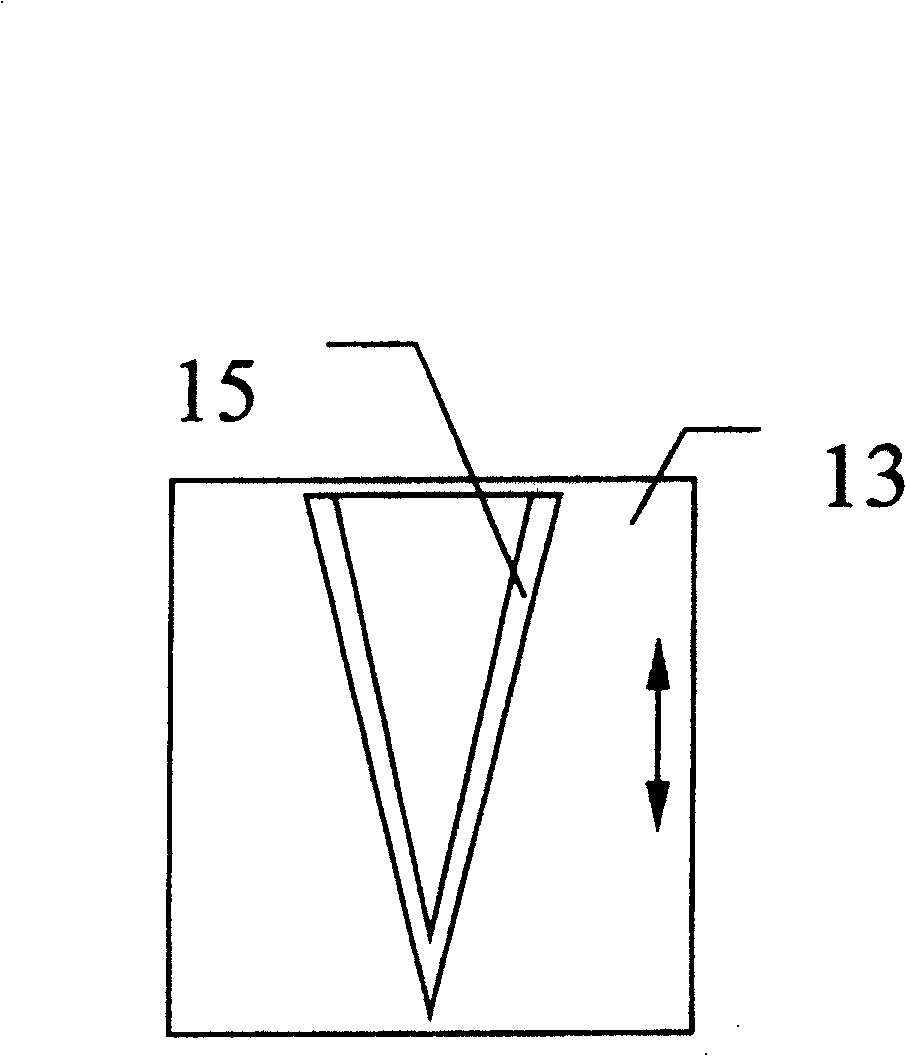
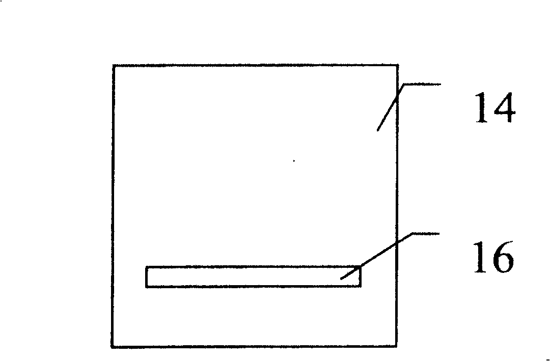
[0022] The optical spatial filter 6 includes: an upper plate 13 and a bottom plate 14, the upper plate 13 and the bottom plate 14 are stacked together, a V-shaped diaphragm 15 is prepared on the body of the upper plate 13, and a word diaphragm 16 is prepared on the body of the bottom plate 14 , The V-shaped aperture 15 is placed opposite to the in-line aperture 16 .

[0023] Laser 1, beam shaping system 2, light reduction plate 3, rectangular grating 4, Fourier transform lens 5, optical spatial filter 6, zoom collimation system 7, restric...


PUM


Abstract

The invention relates to a device for measuring an optical transfer function using an optical spatial filter, comprising a laser (1), a beam shaping system (2), a light reduction plate (3), a rectangular grating (4), a Fourier transform lens (5), an optical Spatial filter (6), zoom collimation system (7), restrictive aperture (8), optical system to be tested (9), variable magnification system (10), area array CCD (11), computer processing system ( 12). The method is to adjust the optical spatial filter to generate double and triple frequency sinusoidal light intensity images on the basis of the fundamental frequency sinusoidal light intensity images, and adjust the light-reducing plate to make the fundamental frequency the same as the double and triple frequency sinusoidal light intensity images. The light intensity of the image is close, compare the amplitude attenuation and phase shift of the sinusoidal light intensity input and output to the area array CCD, and obtain the measured value of the optical transfer function, thus avoiding the difficulty of making a sinusoidal grating; using a laser light source to improve the photometric efficiency; Mathematics The processing is simple; all kinds of optical components adopt common devices, which makes it easy to manufacture. It can be easily configured in the laboratory and can also be mass-produced.

Description

Technical field: [0001] The invention belongs to the field of optical transfer function measurement, and relates to a method and a device for measuring the optical transfer function by using an optical space filter. Background technique: [0002] Modern optical transfer function measuring instruments require area or density sinusoidal gratings according to the optical Fourier analysis method, but the manufacture of sinusoidal gratings is difficult. [0003] The photoelectric Fourier analysis method uses a rectangular grating instead of a sine grating, and removes high-order harmonics by electrical filtering, and performs zero-frequency normalization to extract a sine wave; the Moore fringe method uses the triangular wave generated by Moore fringes to replace the sine wave; the electrical Fourier analysis method , it is necessary to use multiple filters to measure each harmonic; the digital Fourier analysis method also uses a rectangular grating, and uses a computer to perfor...

Claims


Application Information

Patent Timeline
IPC IPC(8): G01M11/02G01M11/00
Inventor 李宏升禹秉熙
Owner CHANGCHUN INST OF OPTICS FINE MECHANICS & PHYSICS CHINESE ACAD OF SCI
Why Eureka
Try Eureka