Combined helix baffle plate shell-and-tube heat exchanger

A technology of shell-and-tube heat exchangers and spiral baffles, which is applied in the direction of heat exchanger types, heat exchanger shells, indirect heat exchangers, etc., and can solve the problems of increasing the load of power equipment and continuous curved surface processing, positioning and drilling , Reduce heat exchange efficiency and other issues, to avoid waste

Inactive Publication Date: 2009-01-21
XI AN JIAOTONG UNIV
View PDF9 Cites 4 Cited by
  • Summary
  • Abstract
  • Description
  • Claims
  • Application Information

AI Technical Summary

Problems solved by technology

[0003] There are many problems in the traditional bow-shaped baffles: (1) The bow-shaped baffles cause the fluid to impact the wall of the shell vertically, causing a large pressure drop along the way and increasing the load on the power equipment; (2) the high-velocity fluid sweeping The heat exchange tube bundle will induce the vibration of the heat exchange tube and shorten the life of the heat exchanger; (3) The flow stagnation dead zone is formed at the junction between the baffle plate and the shell wall, which reduces the heat exchange efficiency and is easy to scale
Compared with discontinuous helical baffles, continuous helical baffles make the flow closer to helical, which can further reduce resistance and leakage, but its processing is more complicated than that of discontinuous helical baffles, especially when the pitch is large , the helical surface near the central axis becomes steeper, which makes continuous curved surface processing and positioning drilling on the curved surface more difficult or even impossible. At present, continuous spiral baffle shell-and-tube heat exchangers mostly use adding The method of installing a core tube with a certain diameter makes it easier for the fluid on the shell side to achieve spiral flow, which reduces the processing difficulty of the continuous spiral baffle to a certain extent, but because the core tube does not pass the fluid, the effective heat transfer area of ​​the heat exchanger is relatively reduced , and the diameter of the core tube increases with the increase of the baffle pitch
On the other hand, the general industrial shell-and-tube heat exchangers are mostly horizontal. Although continuous spiral baffles are used to reduce leakage, when the medium that is easy to scale flows through the shell side, the bottom of the heat exchanger is still Fouling may be formed due to too low flow rate, especially when the helix angle is small, a large amount of fouling is deposited and cannot be removed, which seriously reduces the heat transfer efficiency

Method used


Image

  • Combined helix baffle plate shell-and-tube heat exchanger
  • Combined helix baffle plate shell-and-tube heat exchanger
  • Combined helix baffle plate shell-and-tube heat exchanger

Examples


Embodiment Construction

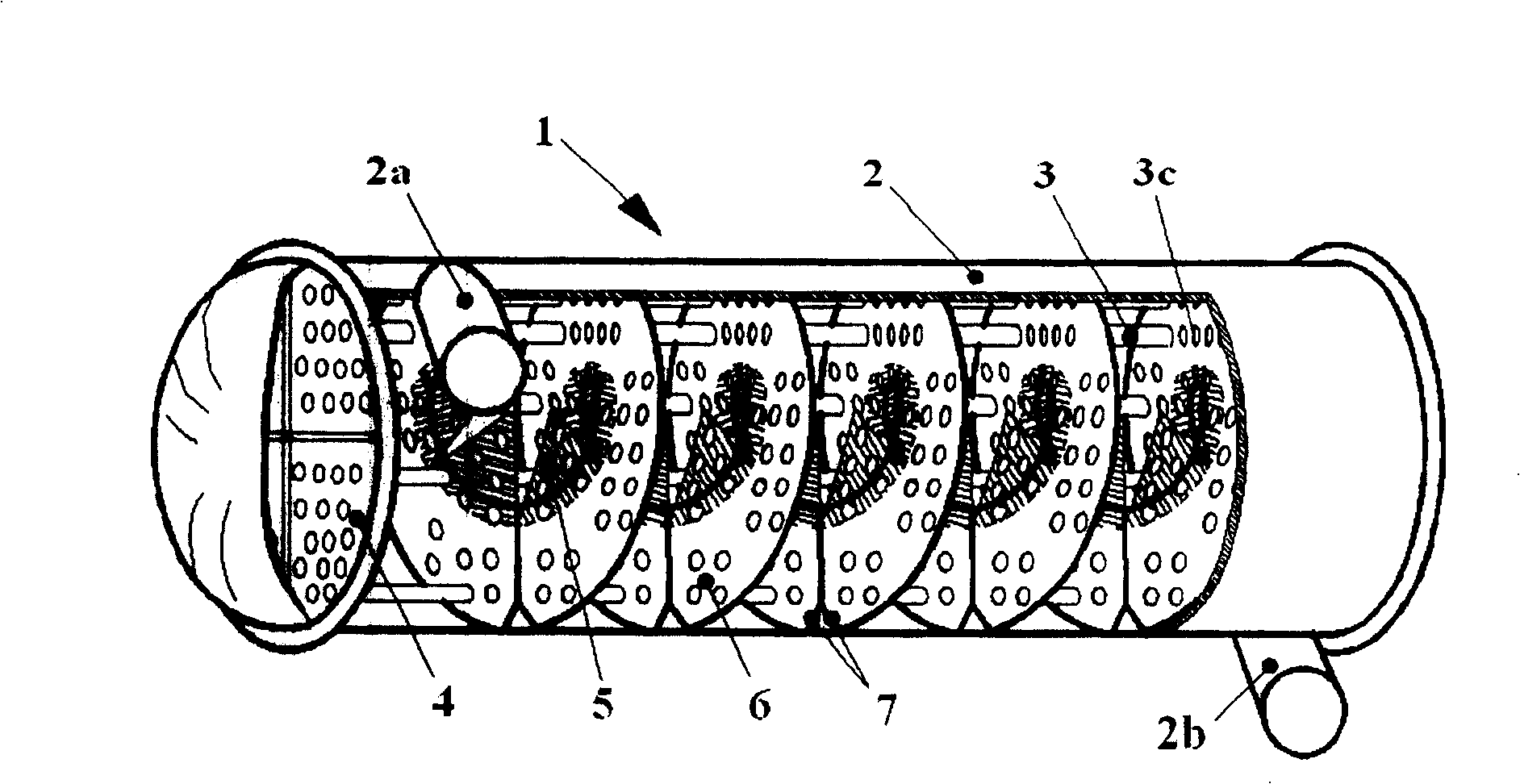
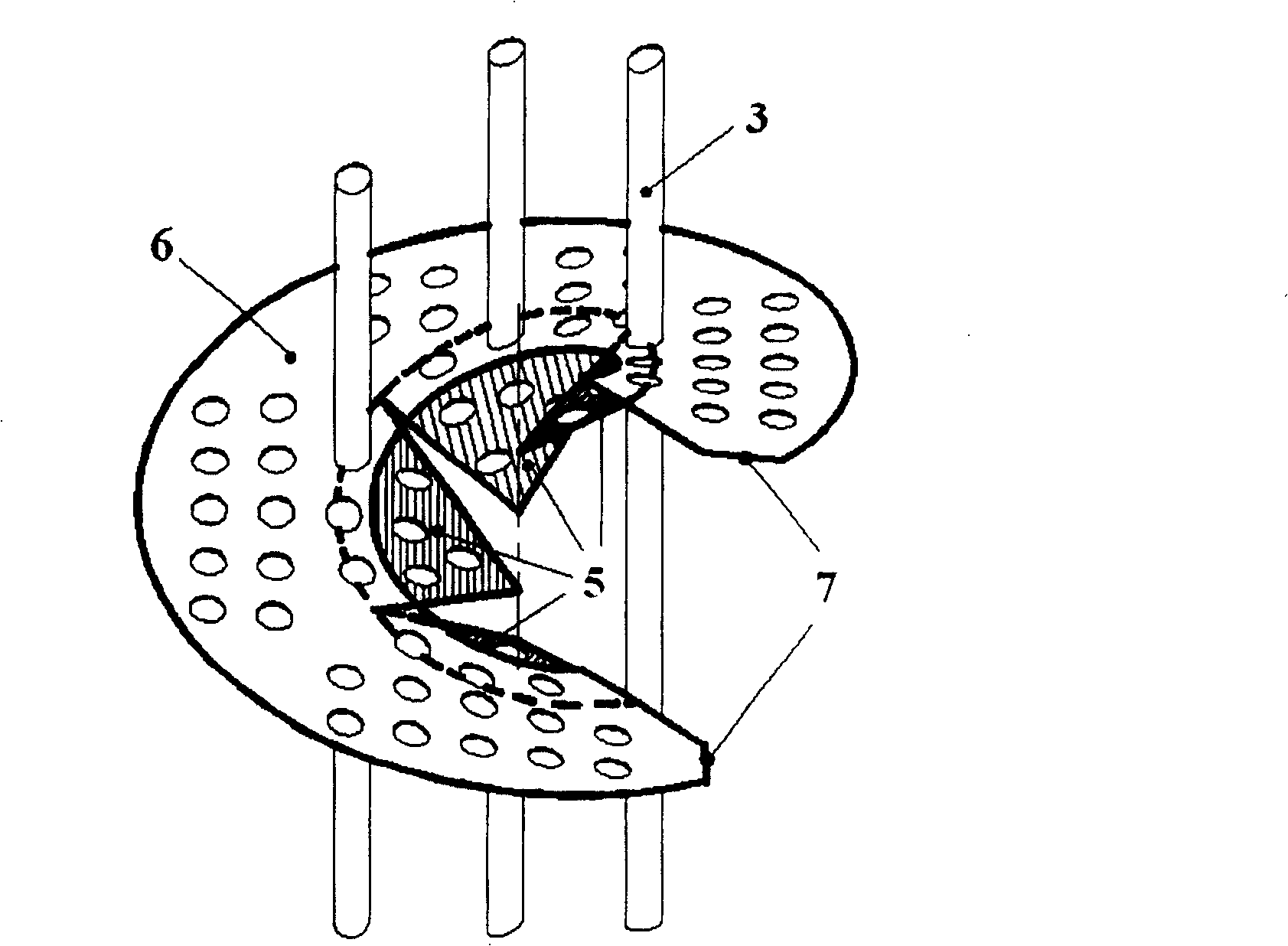
[0024] refer to figure 1 As shown, the combined spiral baffle shell-and-tube heat exchanger 1 of the present invention includes a shell 2, a shell-side inlet pipe 2a, a shell-side outlet pipe 2b, a heat exchange tube bundle 3, a tube sheet 4, and an inner spiral baffle 5 and the outer spiral baffle 6. The shell-side inlet pipe 2a and the shell-side outlet pipe 2b on the shell 2 adopt the form of side-in and side-out, which are installed close to the outer edge of the shell 2, and flow into and out of the shell-side space along the direction tangent to the shell, so that the The fluid on the shell side is more in line with the characteristics of spiral flow, reducing the local resistance caused by the inlet and outlet. The heat exchange tube bundle 3 is interspersed on the inner helical baffle 5 , the outer helical baffle 6 and the two tube sheets 4 located at both ends of the shell. Within each pitch, the inner helical baffle 5 is located in the inner space of the shell 2 In...


PUM


Abstract

The invention discloses a combined screw divert plate tubular heat exchanger, wherein, in one pitch, the screw divert plate is radial divided into inner and outer parts; the central area in the frame has discontinuous inner screw while outside the central area, uses continuous annular screw divert plate to form continuous outer screw; the outer screw divert plate surrounds the inner screw divert plate. For the horizontal heat exchanger, when the medium is accumulated with dirt, the nearby outer screw divert plate is mounted to make the connection at the bottom of heat exchanger, and the outer edge of each connection has a cut at the connected part. The invention can reduce flowing resistance, improve heat exchange efficiency and improve the service life. The invention also provides the method for processing the continuous screw divert plates, to confirm the concentric property of holes of divert plate.

Description

technical field [0001] The invention relates to a shell-and-tube heat exchanger used in petrochemical, energy and power, metallurgy, refrigeration, seawater desalination and other industrial fields, in particular to a combined spiral baffle shell-and-tube heat exchanger and its outer spiral The processing method of the baffle. Background technique [0002] Heat exchangers are one of the important equipment widely used in petrochemical, energy and power, metallurgy, refrigeration, seawater desalination and other industrial fields. Shell-and-tube heat exchangers account for the largest proportion of the total heat exchange equipment, about 55-70 %. It has a simple structure and mainly includes two parts: a heat exchange tube bundle and a shell. One fluid flows in the tube, and the other fluid flows in the shell side outside the tube. The two fluids exchange heat indirectly through the tube wall. [0003] There are many problems in the traditional bow-shaped baffles: (1) The ...

Claims


Application Information

Patent Timeline
Patent Type & Authority Patents(China)
IPC IPC(8): F28D7/16F28F9/22
Inventor 王秋旺张冬洁曾敏吴一宁
Owner XI AN JIAOTONG UNIV
Why Eureka
Try Eureka