Radiator structure
A heat dissipation structure and heat dissipation body technology, applied in cooling/ventilation/heating transformation, instrument cooling, instrument and other directions, can solve the problems of accelerated heat dissipation, damage, unusability, etc., achieve good heat dissipation effect, low cost, and simple production Effect
- Summary
- Abstract
- Description
- Claims
- Application Information
AI Technical Summary
Problems solved by technology
Method used
Image

Examples
Embodiment 1
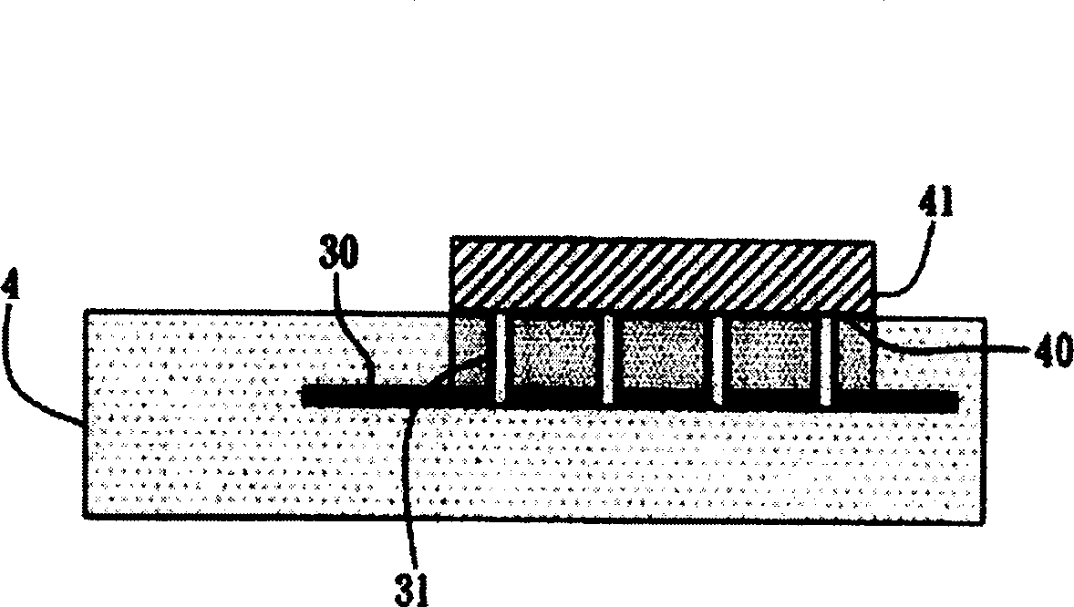
[0020] image 3 Shown is a schematic diagram of Embodiment 1 of the heat dissipation structure of the present invention. The heat dissipation structure is applied to a circuit board 4 having an electrical connection pad 40 for connecting at least one heating element 41 on the surface. The heat dissipation structure includes at least a heat dissipation body 30 and Heat conductor 31. The radiator 30 is embedded in the circuit board 4, the thermal conductor 31 is embedded in the circuit board 4 and connected to the electrical connection pad 40 and the radiator 30, and is connected to the heating element on the electrical connection pad 40. The heat of 41 is conducted to the radiator 30 , and the heat generated by the heating element 41 is dissipated by the radiator 30 .
[0021] The circuit board 4 used in the present invention can be, for example, a multilayer laminated circuit board, and a plurality of electrical connection pads 40 (such as welding pads (Solder Pad)) are forme...
Embodiment 2
[0027] see Figure 4 , which is a schematic diagram of Embodiment 2 of the heat dissipation structure of the present invention. This heat dissipation structure is also applied to a circuit board 4 having an electrical connection pad 40 on the surface for connecting at least one heating element 41 as in Embodiment 1. The heat dissipation structure It also includes at least a radiator 30 and a thermal conductor 31 . The difference between this embodiment 2 and embodiment 1 is that each of the thermal conductors 31 is not only connected to the heat sink 30 by the electrical connection pad 40, but also penetrates to the bottom surface of the circuit board 4, so that the heat sink 30 passes through Each of the heat conductors 31 can further conduct heat to the outside. It is adapted to the general design that the circuit board 4 is arranged in the electronic device and is attached to one side of the case, and the heat conducted from the bottom surface of the circuit board 4 can be...
Embodiment 3
[0029] FIG. 5 is a schematic diagram of Embodiment 3 of the heat dissipation structure of the present invention. This heat dissipation structure is also applied to a circuit board 4 having an electrical connection pad 40 for connecting at least one heating element 41 on the surface as in Embodiment 2. The heat dissipation structure It includes at least a radiator 30 and a thermal conductor 31 . The difference between the present embodiment 3 and the embodiment 2 is that each thermal conductor 31 penetrates beyond the bottom surface of the circuit board 4, and is also connected to a bottom radiator 30' located at the bottom surface of the circuit board 4. In this way, the heat dissipation body 30 can further conduct heat to the bottom heat dissipation body 30' of the outside through the heat conductors 31, thereby further improving heat dissipation efficiency.
PUM
 Abstract
Description
Claims
Application Information
 - R&D
- Intellectual Property
- Life Sciences
- Materials
- Tech Scout
- Unparalleled Data Quality
- Higher Quality Content
- 60% Fewer Hallucinations
Browse by: Latest US Patents, China's latest patents, Technical Efficacy Thesaurus, Application Domain, Technology Topic, Popular Technical Reports.
© 2025 PatSnap. All rights reserved.Legal|Privacy policy|Modern Slavery Act Transparency Statement|Sitemap|About US| Contact US: help@patsnap.com