
Post-shaped element for determining spatial position

A space position and component technology, applied in veterinary instruments, equipment for treating animal teeth, medical science, etc., can solve problems such as plastic deformation of mold materials, misalignment of mold columns, etc., to achieve improved reliability, correct connection position, and stable connection Effect

Inactive Publication Date: 2009-03-11
HERAEUS KULZER
View PDF10 Cites 0 Cited by
  • Summary
  • Abstract
  • Description
  • Claims
  • Application Information

AI Technical Summary

Problems solved by technology

[0004] On the whole, a disadvantage of the known cylindrical elements described is that, when the long axis of the implant and of the artificial recess is tilted, the mold pillar integrated with the solidified molding material can be extracted in the same direction as the mold pillar. The direction of the long axis is the same, that is, the direction in which the fastening section can be taken out from the fastening groove alone. In this inclined case, the removal of the mold material and the mold column can only be realized by virtue of the elasticity of the mold material. At this time, There is a risk that, in the case of large deflections of the cylindrical element, removal from its molded position would lead to plastic deformation of the molding compound, that is to say misalignment of the mold pillar in the molding compound

Method used


Image

  • Post-shaped element for determining spatial position
  • Post-shaped element for determining spatial position
  • Post-shaped element for determining spatial position

Examples


Embodiment Construction

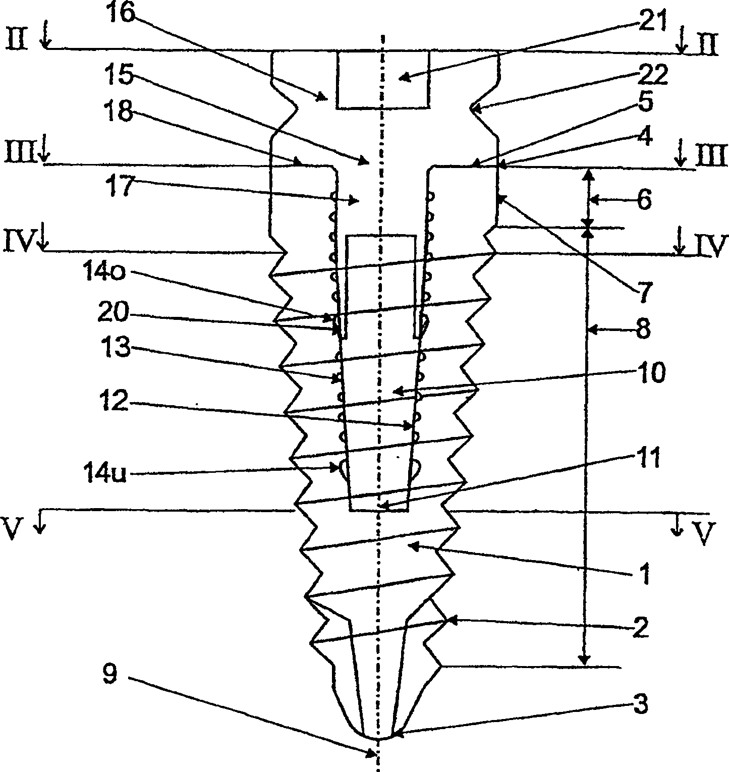
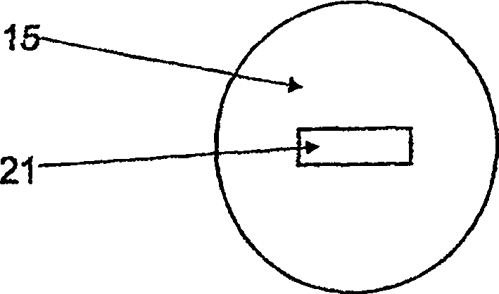
[0030] Figure 1 to Figure 5 Shown is an implant 1 made of titanium having an approximately conical shape with external threads 2 on the outer surface, said implant 1 also having a rounded distal end. End 3 and proximal end 4, this proximal end is constituted by a true circular top surface 5, in a segment 6 adjoining top surface 5, implant 1 has a cylindrical shape with an outer surface 7 precisely polished , in the next threaded segment 8, the implant 1 is tapered, starting from the top surface 5, a fastening groove 10 extends parallel to the long axis 9 of the implant 1 and through the total length of the segment 6 And part of the length of the threaded segment 8.

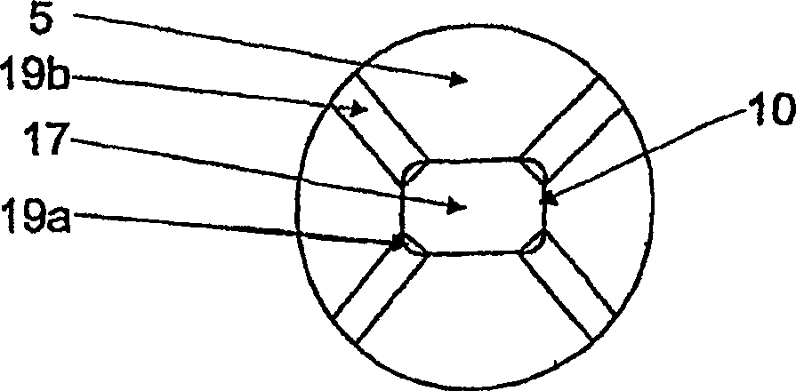
[0031] Such as image 3 As shown, the cross-section of the fastening groove 10 in the range of section 6 is a rounded rectangular shape. Starting from the threaded section 8, the cross-section of the fastening groove 10 gradually becomes smaller downwards. On the bottom 11, the cross section presents a rounded...


PUM


Abstract

A post-shaped element for determining the spatial position of an implant (10), or the opening cross-section of an artificial indentation located in a tooth or in the stroma of a human or animal body, relative to the tissue structures surrounding it, can be introduced with a receiving section (26A) into an adapted receiving recess (10) in the implant (1) or in the artificial indentation, be affixed therein to be torsion resistant and able to again be removed there-from. In a connecting position the post-shaped element protrudes with a cantilever section (26K) beyond the opening cross-section of the receiving recess (10) or artificial indentation. To be able to easily remove the post-shaped element embedded in the impression mass, even in the case of a slanted position of the implant (1) or the longitudinal axis of the artificial indentation in relation to the surrounding tissue structures, it is suggested to ensure that the post-shaped element consists of a bottom portion (24), which can be torsion-resistantly fixated in the receiving recess (10) or the artificial indentation, and a top portion (25), which can be inserted torsion-resistantly in the bottom portion (24) or placed on said portion, wherein the top portion (25), proceeding from the connecting position of the post-shaped element, can be removed in a linear fashion from the bottom portion (24) in various directions.

Description

technical field [0001] The present invention relates to a cylindrical element for determining the spatial position of an implant relative to the tissue structure surrounding the implant, or for determining the opening of an artificial recess in a tooth or in supporting tissue in a human or animal body The cross-section is relative to the spatial position of the surrounding tissue structure of the artificial groove. The columnar element can be inserted into the matching fastening groove with a fastening section, implanted in the implant or artificial groove, and the columnar element can be fixed. In the fastening groove, it can also be moved out again, while the cylindrical element has a cantilever section above the opening cross-section of the fastening groove or the artificial groove. Background technique [0002] In the field of dentistry, a column element of this type is called a mold column, for example, it can be used in dental medicine to determine the state and positi...

Claims


Application Information

Patent Timeline
Patent Type & Authority Patents(China)
IPC IPC(8): A61C8/00A61D5/00A61C9/00A61C13/34A61F2/00
CPCA61C8/008A61C8/0054A61D5/00A61C8/0069A61C8/005A61C8/0066A61C8/0001A61C8/0071
Inventor 米夏埃尔·奥古森曼弗雷德·彼得斯克劳斯·哈泽尔胡恩胡贝图斯·施皮克曼
Owner HERAEUS KULZER
Learn More